Do you have a question about the Trane 4PXFH001BC3HHA and is the answer not in the manual?
Coil must be installed downstream (discharge air) of the furnace.
Indoor unit must provide required airflow for cooling or heat pump.
Follow Installer's Guide for furnaces, heat pumps, and control centers.
Study outline drawing for dimensions and clearance allowances for installation.
Steps for running refrigerant lines including routing, bends, and securing.
Pressurize with nitrogen, check for leaks with soap bubbles, then evacuate.
Clear drain hole and insulate primary drain line to prevent sweating.
Connect secondary drain to a separate line terminating in an easily seen area.
Test drainage of all condensate lines prior to completing installation.
Bulb must be in direct contact, mounted horizontally, at 2 or 10 o'clock, and insulated.
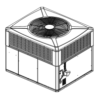
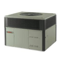
This document is an installer's guide for horizontal, flat "cased" coils, specifically models such as 4PXFH001BC3HHA, 4PXFH003BZ3HHA, 4PXFH004BC3HHA, 4PXFH005BZ3HHA, 4PXFH007BC3HHA, and 4PXFH009BZ3HHA. These coils are designed for use in heating, ventilation, and air conditioning (HVAC) systems, primarily for cooling purposes, or in combination with a Heat Pump outdoor section. The guide emphasizes compliance with national, state, and local codes for all installation phases and stresses the importance of returning the document to the service information pack upon completion of work.
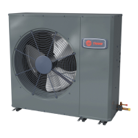
The primary function of these coils is to facilitate heat exchange within an HVAC system, enabling the cooling of indoor air. When used with a Heat Pump outdoor section, they also contribute to the heating cycle. The coils are designed to be installed downstream (discharge air) of a furnace, ensuring that the air passes through the coil after being heated or conditioned by the furnace. This configuration is crucial for optimal system performance, whether for cooling-only applications or combined heat pump systems. The design allows for installation in various setups, including horizontal furnaces (both gas and electric) and vertical upflow furnaces, particularly in situations where top clearance is limited and access to a horizontal duct run is available. The coils are pre-pressurized with dry air (8-12 psig) to ensure integrity upon arrival, and installers are cautioned to relieve this pressure safely before opening connections.
The installation process involves several critical steps to ensure proper function and safety. The coil/enclosure assembly must be integrated into the horizontal duct run, often requiring a fabricated transition duct to connect it to the furnace supply outlet and the main supply air duct. For maximum performance, a transition duct of at least 2 feet in length is recommended. The refrigerant lines and condensate connections can be positioned on either side of the supply air duct, allowing flexibility in airflow direction through the coil. Proper support for the coil/enclosure assembly's weight is essential, and the coil must be kept level, as extra pitch is not required for drainage. Secure connections are paramount to prevent air leakage, which can compromise system efficiency.
When installing in ceiling-mounted applications, specific care must be taken to avoid puncturing the coil or drainpan with screws. Areas such as the back, bottom, front, top center, and the lower 3 inches of the left and right sides of the coil cabinet should be avoided for screw placement. The indoor coil must be evacuated through the refrigerant lines at the outdoor unit before opening service valves, following the detailed evacuation procedure provided in the outdoor unit's Installer's Guide.
The guide also details the installation and brazing of refrigerant lines. Installers are warned not to open the refrigerant valve at the outdoor unit until the lines and coil have been brazed, evacuated, and leak-checked, as this could lead to refrigerant contamination or discharge into the atmosphere. Practical considerations for routing lines, making bends, and securing tubing are provided. Refrigerant lines must be isolated from the structure, and holes sealed weather-tight.
Regular maintenance and proper installation practices are key to the longevity and efficiency of the coil. The guide emphasizes the importance of leak checking all brazed line connections using soap bubbles after pressurizing the lines and indoor coil to 150 PSIG with dry nitrogen. Any leaks must be repaired before evacuating and charging the system according to the outdoor unit's instructions.
Condensate drainage is another critical aspect. The drain pan at the bottom of the coil/enclosure assembly includes female threaded fittings for external connection. While a field-fabricated trap is not strictly required due to the furnace's positive pressure, it is recommended to prevent efficiency loss. The primary drain line should be insulated to prevent sweating, especially in areas where dew point temperatures may be met. A secondary drain line, which does not require a trap, should terminate in an easily visible area for the homeowner, but away from sidewalks or other slip hazard zones. All condensate lines must be tested for proper drainage before completing the installation. Importantly, any unused drain line connections must be plugged, and heat or torches should not be used near drain fittings.
The guide also covers the installation of the TXV (Thermostatic Expansion Valve) sensing bulb, which significantly influences system performance. For horizontal mounting, the bulb should be parallel to the ground, positioned at 2 o'clock or 10 o'clock. For vertical mounting, the capillary tubes should be directed upwards. The sensing bulb must be in direct and continuous contact with a clean, smooth section of the suction/vapor line, mounted horizontally, and insulated from outside air to prevent false readings.
A troubleshooting section for the indoor TXV in cooling mode is provided, guiding installers through a diagnostic process based on sub-cooling, superheat, and airflow measurements. This includes checks for inlet screen debris in the liquid line and instructions for cleaning or replacing components as needed. The guide also advises wrapping the TXV with a wet cloth before brazing and directing the torch away from the wrapped valve to prevent damage. Overall, the document provides comprehensive instructions to ensure a safe, efficient, and reliable installation of the horizontal, flat "cased" coils.
| Model Number | 4PXFH001BC3HHA |
|---|---|
| Category | Air Handlers |
| Phase | 1 |
| Refrigerant Type | R-410A |
| Product Type | Horizontal |
| Nominal Airflow | 400 CFM |
| Cabinet Type | Horizontal |
| Filter Type | Standard |