EasyManua.ls Logo

Trane 4TWB3036C User Manual

Trane 4TWB3036C
28 pages
To Next Page IconTo Next Page
Page #1 background imageLoading...
Page #1 background image
18-BC85D1-2
ALL phases of this installation must comply with NATIONAL, STATE AND LOCAL CODES
IMPORTANT — This Document is customer property and is to remain with this unit. Please return to service informa-
tion pack upon completion of work.
Heat Pumps
These instructions do not cover all variations in systems or provide for every possible contingency to be met in connection with
the installation. Should further information be desired or should particular problems arise which are not covered sufficiently for the
purchaser’s purposes, the matter should be referred to your installing dealer or local distributor.
Note: The manufacturer recommends installing only approved matched indoor and outdoor systems. All of the manufacture’s split
systems are AHRI rated only with TXV/EEV indoor systems. Some of the benefits of installing approved matched indoor and out-
door split systems are maximum efficiency, optimum performance and the best overall system reliability.
4TWB3018–060
Installer’s Guide
Table of Contents
Section 1. Safety ..................................................................................... 2
Section 2. Unit Location Considerations.............................................. 3
Section 3. Unit Preparation .................................................................... 5
Section 4. Setting the Unit ..................................................................... 5
Section 5. Refrigerant Line Considerations ......................................... 6
Section 6. Refrigerant Line Routing ..................................................... 7
Section 7. Refrigerant Line Brazing ...................................................... 8
Section 8. Refrigerant Line Leak Check .............................................10
Section 9. Evacuation ........................................................................... 11
Section 10. Service Valves ................................................................... 11
Section 11. Electrical - Low Voltage .................................................... 13
Section 12. Electrical - High Voltage ................................................... 16
Section 13. Start Up .............................................................................. 17
Section 14. System Charge Adjustment ............................................. 18
Section 15. Checkout Procedures and Troubleshooting ................... 23
Question and Answer IconNeed help?

Do you have a question about the Trane 4TWB3036C and is the answer not in the manual?

Trane 4TWB3036C Specifications

General IconGeneral
BrandTrane
Model4TWB3036C
CategoryHeat Pump
LanguageEnglish

Summary

Section 1. Safety

Electrical Safety Warnings

Highlights dangers of working with live electrical components.

Refrigerant Handling and Pressure Warnings

Covers R-410A refrigerant, POE oil, and high pressure hazards.

Component Temperature and Mechanical Warnings

Alerts to hot compressor domes and service valve operation.

Section 2. Unit Location Considerations

Unit Dimensions and Weight

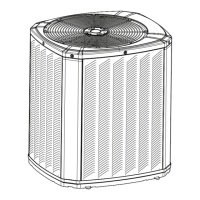
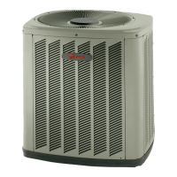
Details physical size and weight of outdoor units.

Refrigerant Piping Limits

Specifies maximum line length and vertical change.

Suggested Locations for Best Reliability

Recommends placement for optimal airflow and noise avoidance.

Cold Climate Considerations

Provides guidance for installations in snowy or freezing environments.

Coastal Considerations

Advises on salt water protection for units near coastlines.

Section 3. Unit Preparation

Prepare The Unit For Installation

Steps for checking and removing the unit from its packaging.

Section 4. Setting the Unit

Pad Installation

Guidelines for selecting and preparing the unit's support pad.

Section 5. Refrigerant Line Considerations

Refrigerant Line and Service Valve Connection Sizes

Table detailing line sizes and valve connection sizes by model.

Factory Charge and Line Length Requirements

Information on initial charge and required line length.

Refrigerant Line Insulation

Emphasizes insulating the vapor line and avoiding metal-to-metal contact.

Reuse Existing Refrigerant Lines

Precautions for using existing refrigerant lines and coils.

Section 6. Refrigerant Line Routing

Precautions

Guidelines for preventing noise and ensuring proper routing of refrigerant lines.

Isolation and Securing of Lines

Details on isolating lines from structural elements and securing them.

Section 7. Refrigerant Line Brazing

Prepare Refrigerant Lines for Brazing

Steps for cleaning and deburring pipe ends before brazing.

Brazing Procedure

Steps for brazing refrigerant lines with dry nitrogen purge and heat protection.

Section 8. Refrigerant Line Leak Check

Check For Leaks

Procedure for pressurizing lines with nitrogen and checking for leaks.

Section 9. Evacuation

Evacuate the Refrigerant Lines and Indoor Coil

Steps for evacuating the system to a specific micron level.

Section 10. Service Valves

Open the Gas Service Valve

Instructions for opening the gas service valve.

Open the Liquid Service Valve

Critical steps for safely opening the liquid line service valve.

Section 11. Electrical - Low Voltage

Low Voltage Maximum Wire Length

Table defining maximum wire lengths for low voltage connections.

Low Voltage Hook-up Diagrams

Wiring diagrams for various indoor units and thermostats.

Defrost Control

Configuration and operation of the defrost control system.

Section 12. Electrical - High Voltage

High Voltage Power Supply

Requirements for the high voltage power supply connection.

High Voltage Disconnect Switch

Guidance on installing a separate disconnect switch.

High Voltage Ground

Instructions for proper grounding of the outdoor unit.

Section 13. Start Up

System Start Up

Step-by-step procedure for powering on and starting the unit.

Section 14. System Charge Adjustment

Temperature Measurements

Procedures for measuring indoor and outdoor temperatures for charging.

Subcooling Charging Method (>55°F)

Adjusting charge using subcooling for ambient temps above 55°F.

Charging Method (<55°F Heating Only)

Adjusting charge in heating mode for ambient temps below 55°F.

Section 15. Checkout Procedures and Troubleshooting

Operational and Checkout Procedures

Final checks and operational procedures after installation.

Troubleshooting System Faults

Guide to diagnosing and resolving system faults and issues.

Related product manuals