EasyManua.ls Logo

Trane 4TWB3 User Manual

Trane 4TWB3
8 pages
To Next Page IconTo Next Page
Page #1 background imageLoading...
Page #1 background image
ALL phases of this installation must comply with NATIONAL, STATE AND LOCAL CODES
IMPORTANT This Document is customer property and is to remain with this unit. Please return to service information
pack upon completion of work.
Installer’s Guide
The Weathertron
®
Heat Pump has been designed and
manufactured to withstand and operate in severe winter
conditions. However, there are precautionary steps which
should be taken at the time of installation which will help
assure the efficient operation of the unit. It is recom-
mended that these precautions be taken for units
being installed in areas where snow accumulation and
prolonged below freezing temperatures occur.
1. Units should be elevated 3 to 12 inches above the pad or
rooftop, depending on local weather. This additional
height will allow better drainage of snow and ice (melted
during defrost cycle) prior to its refreezing. This should
prevent a build-up of ice around the unit which occurs
when unit is not elevated. Insure that drain holes in
unit base pan are not obstructed preventing drain-
ing of defrost water.
2. If possible, avoid locations that are likely to accumulate
snow drifts. If not possible, a snow drift barrier should be
installed around the unit to prevent a build-up of snow on
Heat Pumps
4TWB3
These instructions do not cover all variations in
systems nor provide for every possible contingency
to be met in connection with installation. All phases
of this installation must comply with NATIONAL,
STATE AND LOCAL CODES. Should further informa-
tion be desired or should particular problems arise which
are not covered sufficiently for the purchaser’s purposes,
the matter should be referred to your installing dealer or
local distributor.
A. GENERAL
WARNING
!
This information is intended for use by individuals posses-
sing adequate backgrounds of electrical and mechanical ex-
perience. Any attempt to repair a central air conditioning
product may result in personal injury and or property dam-
age. The manufacturer or seller cannot be responsible for
the interpretation of this information, nor can it assume any
liability in connection with its use.
NOTICE:
Trane has always recommended installing Trane approved
matched indoor and outdoor systems.
The benefits of installing approved matched systems are
maximum efficiency, optimum performance and best
overall system reliability.
WARNING
!
These units use R-410A refrigerant which operates at 50 to
70% higher pressures than R-22. Use only R-410A approved
service equipment. Refrigerant cylinders are painted a
“Rose” color to indicate the type of refrigerant and may
contain a “dip” tube to allow for charging of liquid refriger-
ant into the system. All R-410A systems use a POE oil that
readily absorbs moisture from the atmosphere. To limit this
“hygroscopic” action, the system should remain sealed
whenever possible. If a system has been open to the at-
mosphere for more than 4 hours, the compressor oil must
be replaced. Never break a vacuum with air and
always
change the driers when opening the system for component
replacement. For specific handling concerns with R-410A
and POE oil, reference Retrofit Bulletin TRN-APG02-EN.
Check for transportation damage after unit is uncrated.
Report promptly, to the carrier, any damage found to the unit.
To determine the electrical power requirements of the unit,
refer to the nameplate of the unit. The electrical power
available must agree with that listed on the nameplate.
1
5 FT. ABOVE UNIT — UNRESTRICTED
CAUTION
!
UNIT CONTAINS R-410A REFRIGERANT!
R-410A OPERATING PRESSURE EXCEEDS THE
LIMIT OF R-22. PROPER SERVICE EQUIPMENT IS
REQUIRED. FAILURE TO USE PROPER SERVICE
TOOLS MAY RESULT IN EQUIPMENT DAMAGE OR
PERSONAL INJURY.
SERVICE
USE ONLY R-410A REFRIGERANT AND
APPROVED POE COMPRESSOR OIL.
SSP-SVN03A-EN
18-BC61D1-1
Question and Answer IconNeed help?

Do you have a question about the Trane 4TWB3 and is the answer not in the manual?

Trane 4TWB3 Specifications

General IconGeneral
BrandTrane
Model4TWB3
CategoryHeat Pump
LanguageEnglish

Summary

Heat Pumps Installation Guide

General Installation Information

Provides general information for installers, including experience requirements and manufacturer responsibilities.

General Safety Warnings

Highlights critical safety warnings regarding electrical and mechanical experience and potential hazards.

Recommended System Matching

Recommends installing Trane approved matched indoor and outdoor systems for optimal performance.

R-410A Refrigerant Handling and Safety

Details safety precautions for R-410A refrigerant, higher pressures, and POE oil requirements.

Winter Operation Precautions

Advises on steps to ensure efficient operation in severe winter conditions, focusing on snow accumulation.

Unit Location and Refrigerant Line Installation

Basepan Tab Removal

Instructions on removing basepan tabs when taking the unit off the pallet.

Unit Placement and Clearance Requirements

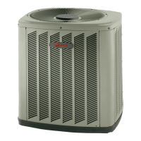
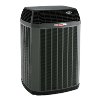
Covers unit placement, support pad requirements, and clearance for airflow and service access.

Installing Refrigerant Lines

Details on routing, bending, and insulating refrigerant lines for proper installation.

Compressor Dome Temperature Warning

Warns that compressor dome temperatures can be hot, posing a burn risk.

Service Valve Operation Overview

Explains the operation of brass liquid and gas line service valves.

Refrigerant Line Brazing and System Checks

Brazing Refrigerant Lines

Step-by-step guide for brazing refrigerant lines, including precautions and purging.

Leak Check and Evacuation Procedures

Details leak checking, system evacuation, and venting prohibition for R-410A systems.

Required Tools for Valve Operation

Lists the specific tools required for opening and closing service valves.

Electrical Connections and Defrost Control

Electrical Connection Requirements

Covers power wiring, grounding, disconnect switches, and low voltage wiring for the unit.

Low Voltage Wiring Lengths

Specifies maximum lengths for low voltage wiring based on wire gauge.

Defrost Control Operation

Explains the demand defrost control, sensors, and fault identification methods.

Defrost Control Checkout

Details normal operation checks for the defrost control, including LED status and voltage checks.

Compressor Start-up Procedure

Outlines the procedure for starting the compressor, including thermostat settings and power application.

Operational and Checkout Procedures

References final operational checks and charge adjustments found elsewhere in the manual.

System Components and Troubleshooting

Electric Heaters Installation

Instructions for installing electric heaters within the air handling device.

Start Control Components

Information on factory-installed or field-installed quick start components for the unit.

Outdoor Thermostat Installation

Details for field installation of an outdoor thermostat (TAYSTAT250B).

Seacoast Salt Shield Requirement

Requirement for adding a Seacoast Kit for units installed near salt water.

Troubleshooting Chart

A chart listing system faults and potential causes for diagnosis.

Typical Field Hook-up Diagrams

Wiring diagrams illustrating typical field connections for thermostats and air handlers.

Refrigerant Charging Procedures

Subcooling Charging Above 55°F OD Ambient

Recommended method for charging systems in cooling mode above 55°F outdoor ambient.

R-410A Refrigerant Charging Chart

Chart providing design subcooling values based on liquid temperature and pressure.

Subcooling Charging Corrections

Table for correcting subcooling charge based on refrigerant line length and height.

Subcooling Charging Below 55°F OD Ambient

Recommended charging method for heating mode below 55°F outdoor ambient.

Unit Dimensions and Mounting

4TWB3 Outline Drawing

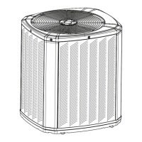
Provides outline dimensions and specifications for various 4TWB3 models.

Service Panel Clearances

Details electrical and refrigerant component clearances required per codes.

Mounting Hole Locations

Diagrams showing mounting hole locations for different base sizes.

Checkout Procedure and System Operation

Final Checkout Procedure Checklist

A checklist of recommended checks after installation is completed.

Supply Registers and Return Grilles

Ensures supply registers and return grilles are open and unobstructed.

Thermostat Accuracy Check

Instructions to check thermostat accuracy against a reliable thermometer.

System Operation Modes

Procedure to operate the complete system in each mode to ensure safe operation.

Related product manuals