EasyManua.ls Logo

Trane 4TWX6 - User Manual

Trane 4TWX6
24 pages
Print Icon
To Next Page IconTo Next Page
Loading...
18-AC105D1-1D-EN
ALL phases of this installation must comply with NATIONAL, STATE AND LOCAL CODES
IMPORTANT — This Document is customer property and is to remain with this unit. Please return to service informa-
tion pack upon completion of work.
Heat Pumps
These instructions do not cover all variations in systems or provide for every possible contingency to be met in connection with
the installation. Should further information be desired or should particular problems arise which are not covered sufficiently for the
purchaser’s purposes, the matter should be referred to your installing dealer or local distributor.
Note: The manufacturer recommends installing only approved matched indoor and outdoor systems. All of the manufacture’s split
systems are A.H.R.I. rated only with TXV/EEV indoor systems. Some of the benefits of installing approved matched indoor and
outdoor split systems are maximum efficiency, optimum performance and the best overall system reliability.
4TWX6
Installer’s Guide
Table of Contents
Section 1. Safety ..................................................................................... 2
Section 2. Unit Location Considerations ............................................. 3
Section 3. Unit Preparation.................................................................... 5
Section 4. Setting the Unit ..................................................................... 5
Section 5. Refrigerant Line Considerations ......................................... 6
Section 6. Refrigerant Line Routing ..................................................... 7
Section 7. Refrigerant Line Brazing ...................................................... 8
Section 8. Refrigerant Line Leak Check ............................................. 10
Section 9. Evacuation .......................................................................... 11
Section 10. Service Valves .................................................................. 11
Section 11. Electrical - Low Voltage ................................................... 12
Section 12. Electrical - High Voltage .................................................. 15
Section 13. Start Up.............................................................................. 16
Section 14. System Charge Adjustment............................................. 17
Section 15. Checkout Procedures and Troubleshooting .................. 23
Question and Answer IconNeed help?

Do you have a question about the Trane 4TWX6 and is the answer not in the manual?

Summary

Safety Information and Warnings

General Safety Precautions

Essential safety guidelines and warnings for installation and service.

Unit Location Considerations

Unit Dimensions and Weight

Details unit dimensions and weight for proper placement and support.

Refrigerant Piping Limits

Specifies maximum refrigerant line length and vertical change.

Optimal Outdoor Unit Placement

Recommendations for unit placement to ensure airflow and avoid operational issues.

Cold Climate Installation Precautions

Guidelines for installing units in areas with snow and freezing temperatures.

Coastal Environment Installation

Advice for installing units near salt water environments.

Unit Preparation for Installation

Initial Unit Preparation Steps

Steps for checking unit condition and removing it from the pallet.

Setting the Outdoor Unit

Outdoor Unit Pad Installation Guidelines

Key considerations for installing the unit on a support pad.

Refrigerant Line Considerations

Refrigerant Line and Valve Sizes

Specifies connection sizes for refrigerant lines and service valves.

Factory Refrigerant Charge Details

Information on the factory charge and when adjustments are needed.

Refrigerant Line Length and Lift

Guidance on measuring line length and vertical change for charging.

Refrigerant Line Insulation Requirements

Importance of insulating the vapor line and preventing metal-to-metal contact.

Reusing Existing Refrigerant Lines

Precautions and checks when reusing existing refrigerant lines.

Refrigerant Line Routing

Refrigerant Line Routing Precautions

Steps to prevent noise transmission and ensure proper line routing.

Refrigerant Line Brazing

Steps for Brazing Refrigerant Lines

Detailed procedure for preparing and brazing refrigerant lines.

Refrigerant Line Leak Check

Performing Refrigerant Line Leak Check

Procedure for pressurizing and checking refrigerant lines for leaks.

System Evacuation

Evacuating Lines and Indoor Coil

Steps for achieving proper vacuum levels in the system.

Service Valve Operation

Opening the Gas Service Valve

Procedure for opening the gas service valve correctly.

Opening the Liquid Service Valve

Procedure and caution for opening the liquid service valve.

Low Voltage Electrical Connections

Low Voltage Wire Length Limits

Maximum allowable lengths for low voltage wiring based on gauge.

Low Voltage Wiring Diagrams

Diagrams illustrating low voltage hook-up for different thermostat types.

Defrost Control Operation and Checkout

Details on defrost control settings and operational checks.

High Voltage Electrical Connections

High Voltage Power Supply Requirements

Guidelines for connecting high voltage power supply and compliance.

High Voltage Disconnect Switch Installation

Recommendation for installing a separate disconnect switch.

High Voltage Grounding

Requirements for grounding the outdoor unit.

System Start Up Procedure

Initial System Start Up Steps

Step-by-step guide for powering up and starting the unit.

System Charge Adjustment

Temperature Measurements for Charging

How to measure temperatures for subcooling charge adjustment.

Subcooling Charging (Cooling > 55°F)

Procedure for adjusting charge using subcooling in cooling mode.

Charge Adjustment (Heating Mode < 55°F)

Method for adjusting charge in heating mode below 55°F outdoor.

Checkout Procedures and Troubleshooting

Final Operational and Checkout Procedures

Final inspection and operational checks for system performance.

System Faults and Troubleshooting Guide

Guide to identifying and resolving system faults based on symptoms.

Overview

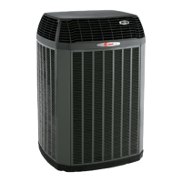
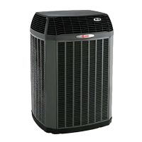
This document is an Installer's Guide for Trane 4TWX6 series heat pumps, identified by the model number 18-AC105D1-1D-EN. It provides comprehensive instructions for the installation, startup, and basic troubleshooting of these outdoor heat pump units. The guide emphasizes compliance with national, state, and local codes throughout all installation phases.

Function Description:

The Trane 4TWX6 heat pumps are outdoor condensing units designed to work as part of a split system for central air conditioning and heating. They utilize R-410A refrigerant and are intended to be matched with approved indoor evaporative coils and TXV/EEV indoor systems for optimal efficiency, performance, and reliability. The units are factory charged with refrigerant sufficient for the outdoor unit, 15 feet of connecting line, and the smallest indoor evaporative coil match. Adjustments to the charge are necessary if line lengths exceed 15 feet or if a larger indoor coil is installed. The guide covers both cooling and heating modes, including specific instructions for subcooling charging in cooling mode (above 55°F outdoor temperature) and weigh-in charging in heating mode (below 55°F outdoor temperature).

Important Technical Specifications:

  • Refrigerant Type: R-410A. This refrigerant operates at 50-70% higher pressures than R-22, requiring R-410A approved service equipment.
  • Compressor Oil: POE oil, which readily absorbs moisture. Systems should remain sealed whenever possible, and compressor oil must be replaced if the system has been open to the atmosphere for more than 4 hours. Driers must be changed when opening the system for component replacement.
  • Refrigerant Line Length Limits: Maximum length of refrigerant lines from outdoor to indoor unit should not exceed 60 feet.
  • Vertical Change Limits: Maximum vertical change should not exceed 60 feet. For longer line lengths, reference specific Trane application guides.
  • Low Voltage Wiring: Maximum wire lengths vary by gauge: 18 AWG (150 ft), 16 AWG (225 ft), 14 AWG (300 ft).
  • Defrost Termination Temperature: As shipped, defrost terminates at 47°F. Cutting Jumper J2 on the defrost board allows for a higher termination temperature of 70°F.
  • Unit Dimensions and Weight:
    • 4TWX6018H, 4TWX6024H: 38 x 30 x 33 inches, 174 lbs.
    • 4TWX6030H, 4TWX6036H: 43 x 34 x 37 inches, 218-219 lbs.
    • 4TWX6042H, 4TWX6048H, 4TWX6060H: 52 x 34 x 37 inches, 247-270 lbs. (Weights are estimated).
  • Service Valve Connection Sizes: Vary by model, but typically include 3/4", 7/8", or 1-1/8" for vapor lines and 3/8" for liquid lines.

Usage Features:

  • Installation Flexibility: The guide provides considerations for various installation scenarios, including rooftop mounting and cold climate installations, recommending elevation (3-12 inches) to prevent snow accumulation and obstruction of drain holes.
  • Refrigerant Line Routing: Detailed instructions for routing refrigerant lines, emphasizing isolation from building structures and ductwork to prevent vibration transmission and noise. It specifies securing vapor lines with isolators every 8 ft and liquid lines to vapor lines every 8 ft.
  • Brazing Procedures: Step-by-step instructions for brazing refrigerant lines, including deburring, cleaning, purging with dry nitrogen, and protecting valve bodies from heat damage.
  • Leak Check and Evacuation: Procedures for pressurizing lines with dry nitrogen to 150 PSIG for leak checking and evacuating the system to a minimum of 350 microns.
  • Service Valve Operation: Instructions for safely opening the gas and liquid line service valves, emphasizing caution when opening the liquid line valve to prevent abrupt release of system charge.
  • Electrical Hook-up: Low voltage wiring diagrams for thermostats and air handlers (TEM 3, 4, 6, 8 and TAM 4, 5, 7, 9 series) and high voltage wiring requirements, including the need for a separate disconnect switch and proper grounding.
  • System Start-Up: A sequence of steps for initial system startup, including setting the thermostat to OFF, applying power, waiting one hour if a crankcase heater is used and ambient temperature is below 70°F, and then setting the thermostat to ON.
  • Charge Adjustment: Detailed methods for adjusting the refrigerant charge based on outdoor temperature, using subcooling in cooling mode (above 55°F) or weigh-in in heating mode (below 55°F). Charts are provided to determine the final subcooling value based on line length and lift. A stabilization period of 20 minutes is required after any charge adjustment.
  • Pre-Installation Inspection: Checking for shipping damage and reporting it to the carrier.
  • Refrigerant Line Integrity: For existing lines, ensuring all joints are brazed (not soldered) and that lines are free of leaks, acid, and oil.
  • Post-Installation Checkout: A comprehensive checklist of operational and checkout procedures to ensure proper performance, including verifying refrigerant lines, insulation, securing lines, sealing passages, checking electrical connections, observing fan operation, ensuring drain line functionality, confirming open registers/grilles, filter installation, correct airflow settings, and operating the system in all modes.
  • Troubleshooting Guide: A detailed table of "System Faults" categorizing issues by "Refrigerant Circuit" and "Electrical," with columns indicating "What to Check," "Mode" (Cooling/Heating), "Primary Causes," "Secondary Causes," and "3 Phase Only" for various symptoms like head pressure too high/low, suction pressure too high/low, liquid refrigerant floodback, coil frosting, compressor/fan won't start, compressor hums, compressor cycles on IOL, ID blower won't start, defrost issues, and unit icing up. This table helps installers diagnose and resolve common problems.
  • Documentation: The guide is intended to remain with the unit in the service information pack, and installers are required to record system information (pressures, temperatures, outdoor model number, etc.) after charging for future reference.

Trane 4TWX6 Specifications

General IconGeneral
BrandTrane
Model4TWX6
CategoryHeat Pump
LanguageEnglish

Related product manuals