Do you have a question about the Trane 4TWB3024D and is the answer not in the manual?
Details unit dimensions and estimated weight for various models.
Specifies maximum refrigerant line length and vertical change limits.
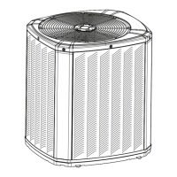
Provides guidance on optimal outdoor unit placement for performance and longevity.
Offers precautions for installing units in areas with snow and freezing temperatures.
Addresses requirements for units installed near salt water environments.
Outlines steps for preparing the unit before installation, including damage checks.
Details requirements for installing the outdoor unit on a support pad.
Provides a table of connection sizes for refrigerant lines and service valves by model.
Explains the factory refrigerant charge and when adjustments are necessary.
Instructs users to determine and record required refrigerant line length and lift.
Emphasizes the importance of insulating the vapor line and preventing metal-to-metal contact.
Provides precautions for using existing refrigerant lines and ensuring compatibility.
Details precautions for routing refrigerant lines to prevent noise and vibration transmission.
Provides step-by-step instructions for brazing refrigerant lines.
Details the procedure for checking refrigerant lines for leaks using nitrogen and soapy solution.
Explains the process of evacuating refrigerant lines and the indoor coil to a specific micron level.
Provides instructions for opening the gas service valve.
Details the procedure for opening the liquid service valve with caution.
Specifies the maximum allowable lengths for low voltage wiring based on wire gauge.
Illustrates low voltage wiring diagrams for communicating and variable speed furnace hook-ups.
Shows the low voltage wiring connections for the TAM7 Air Handler.
Illustrates the low voltage wiring connections for the TAM4 Air Handler.
Depicts the low voltage wiring for the GAM5 Air Handler model.
Shows the low voltage wiring connections for the GAM2 Air Handler.
Illustrates the low voltage wiring for the GAF2 Air Handler.
Details the low voltage wiring connections for the GAF2-36M Air Handler.
Explains defrost control settings, pin identification, and checkout procedures.
Identifies the function of various pins on the defrost control board.
Outlines the steps for checking the defrost control's operation.
Discusses requirements for the high voltage power supply and compliance with codes.
Recommends installing a separate disconnect switch for high voltage connections.
Specifies the requirement to ground the outdoor unit according to codes.
Provides a step-by-step guide for starting up the installed system.
Guides on taking necessary temperature measurements for charging.
Details the subcooling method for charging in cooling mode above 55°F ambient.
Explains charging for heating mode below 55°F outdoor temperature.
Lists operational and checkout procedures for ensuring proper system performance.
Provides a system faults table to help diagnose and troubleshoot common issues.
| Model | 4TWB3024D |
|---|---|
| Type | Heat Pump |
| Cooling Capacity (BTU/h) | 24000 |
| Heating Capacity (BTU/h) | 24000 |
| Refrigerant | R-410A |
| Voltage | 208/230 |
| Phase | 1 |
| Compressor Type | Scroll |