18-BC85D1-2 15
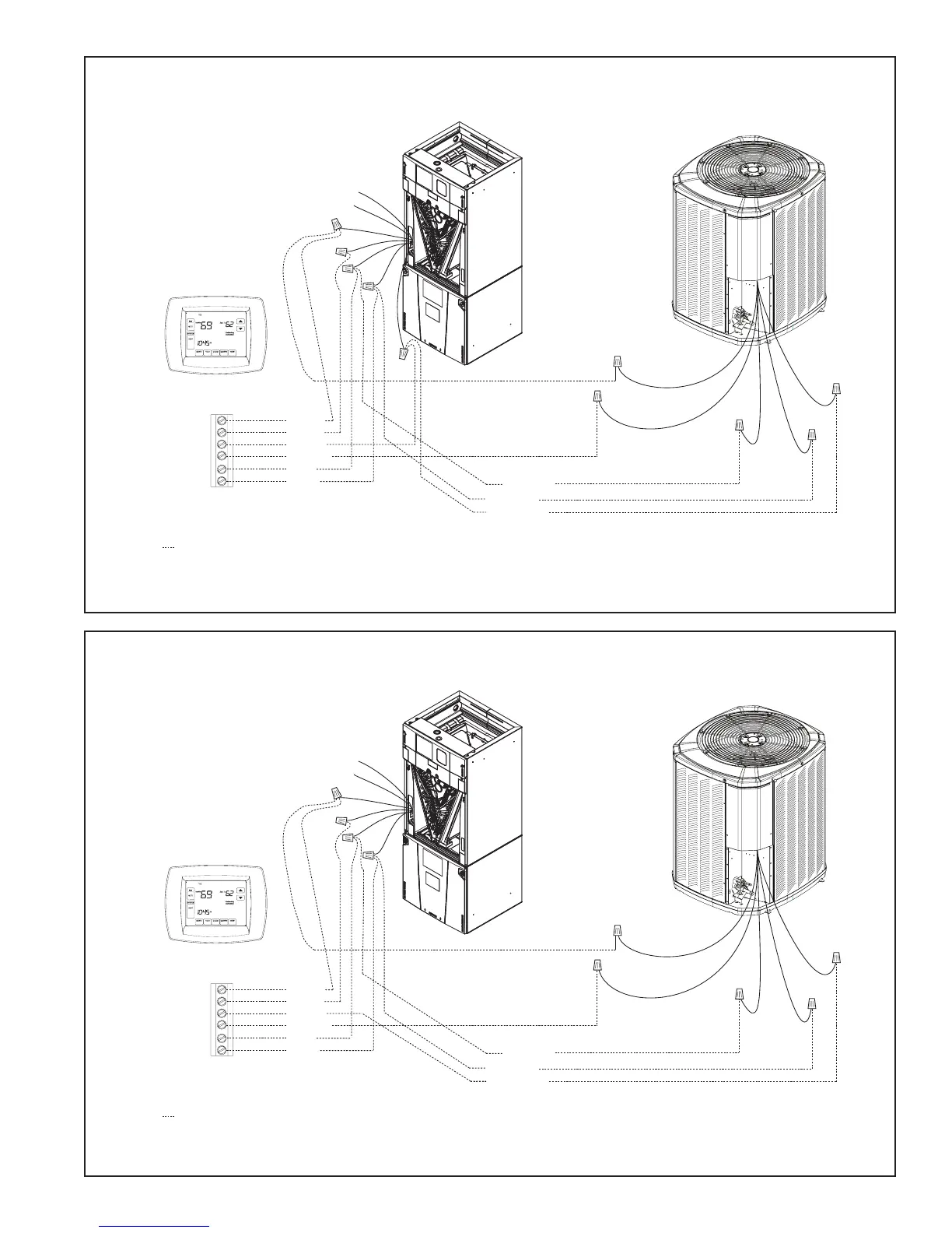
GAM5 Air Handler
Hook-up Diagram
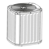
GAM2 Air Handler
Hook-up Diagram
Red
Yellow
Green
White
Blue
Orange
Yellow
Green
White
Blue
B
B - Blue
R - Red
W
G
Y
Y - Yellow
R
Red
O
Orange
Comfort Control
Air Handler
Field wiring
Yellow
Blue
Black
(X2)
Red
Orange
Heat Pump
Red
Blue
Green
W2 Pink
W3 Brown
W1 White
Yellow
• * For multiple stages of electric heat, jumper W1, W2, and W3 together if comfort control has only one stage of heat
• Some models have a terminal strip. Refer to air handler Installer’s Guide.
Red
Yellow
Green
White
Blue
Orange
Yellow
Green
White
Blue
B
B - Blue
R - Red
W
G
Y
Y - Yellow
R
Red
O
Orange
Comfort Control
Air Handler
Field wiring
Yellow
Blue
Black
(X2)
Red
Orange
Heat Pump
Red
Blue
Green
W2 Pink
W3 Brown
W1 White
• * For multiple stages of electric heat, jumper W1, W2, and W3 together if comfort control has only one stage of heat