14 18-BC85D1-2
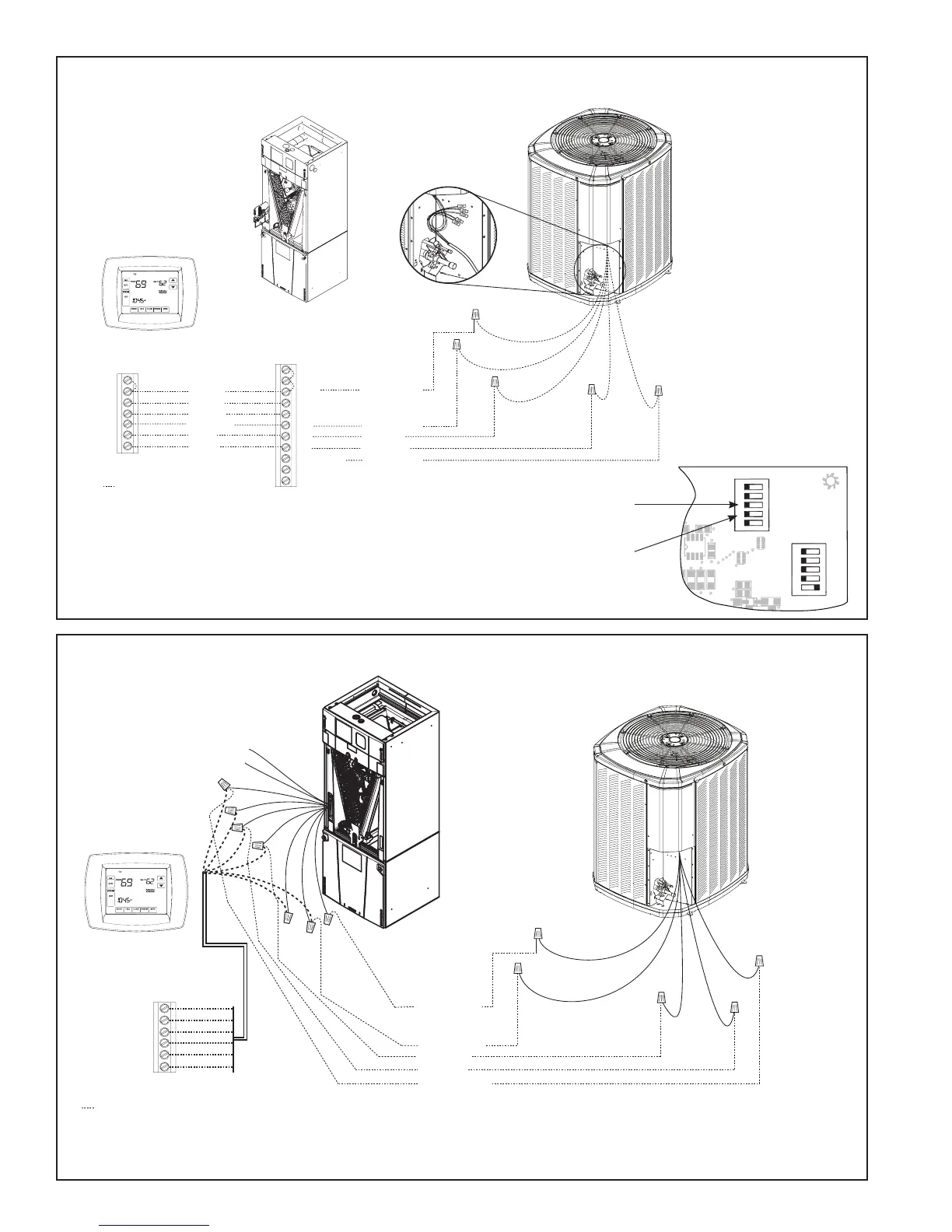
TAM7 Air Handler
Hook-up Diagram
TAM4 Air Handler
Hook-up Diagram
1
1
12345
12345
HP
2(Compressor)
2(Stages)
AC (S ystem)
}
OUTDOOR
Capacity (Tons)
OUTDOOR
}
Torque
CFM/Ton
Cool Of fDelay
}
INDOOR
CFM
+12V
R13
R14
R1
R4
1
U1
RNET 1
S1
on
on
S2
RNET 2
R
6
C22
C19
C
15
C
12
C18
C21
C10
D9
L1
R22
Must configure to
“OFF” for HP Units.
Must configure to “OFF” for
single-stage compressors.
Control Board
Comfort Control
Yellow
Green
White
Blue
B
W
G
Y
R
Red
O
Orange
Yellow
Blue
Black
(X2)
Red
Orange
Heat Pump
B - Blue
Y - Yellow
R - Red
O - Orange
W1 - White
Air Handler
Red
Blue
Yellow YI
Purple YO
Orange
Green
W2 Pink
W3 Brown
W1 White *
• * For multiple stages of electric heat, jumper W1, W2, and W3 together if comfort control has only one stage of heat
• YI and YO connections must be made as shown for proper operation, freeze protection, and internally mounted condensate
overflow circuits to work properly
• Internally mounted condensate switch is optional and must be ordered separately
• If a 3rd party condensate overflow switch is installed, it should be wired between Y of the thermostat and YI of the EEV control.
• Some models have a terminal strip. Refer to air handler Installer’s Guide.
Comfort Control
Air Handler
Neatly bundle all low voltage
wires as shown.
Field wiring
Yellow
Blue
Black
(X2)
Red
Orange
Red
Yellow
Orange
Green
White
Blue
B
B - Blue
W
X2
G
Y1
Y1 - Yellow
R
O
O
R
B
YI
W1
YO
DH/BK
G
W2
W3
R - Red
O - Orange
(In)
(Out)
W1 - White