14 18-BC95D1-5E-EN
STEP 3 - Stabilize the system by operating for a minimum of 20 minutes.
At startup, or whenever charge is removed or added, the system must be operated for a minimum of 20 minutes to
stabilize before accurate measurements can be made.
STEP 4 - Measure the liquid line temperature and pressure at the outdoor unit’s service valve.
Measured Liquid Line Temp = __________ º F
Liquid Gage Pressure = __________ PSIG
Final Subcooling Value = __________ º F
STEP 5 - Use the final subcooling value, refrigerant temperature and pressure from STEP 4, to determine the
proper liquid gage pressure using Table 14.2.
Example: Assume a 12º F Final Subcooling value and liquid temp of 90º F.
1. Locate 12º F Final Subcooling in Table 14.2.
2. Locate the Liquid Temperarature (90º F) in the left column.
3. The Liquid Gage Pressure should be approximately 327 PSIG. (This is the shown as the intersection of the
Table 14.2
8910 11 12 13 14
179 182 185 188 191 195 198
195 198 201 204 208 211 215
211 215 218 222 225 229 232
229 232 236 240 243 247 251
247 251 255 259 263 267 271
267 271 275 279 283 287 291
287 291 296 300 304 309 313
309 313 318 322 327 331 336
331 336 341 346 351 355 360
355 360 365 370 376 381 386
381 386 391 396 402 407 413
407 413 418 424 429 435 441
435 441 446 452 458 464 470
464 470 476 482 488 495 501
495 501 507 514 520 527 533
R-410A REFRIGERANT CHARGING CHART
55
60
65
70
75
80
85
90
95
100
105
110
115
120
125
LIQUID
TEMP
(
°
F)
FINAL SUBCOOLING (
°
F)
LIQUID GAGE PRESSURE (PSI)
From Dwg. D154557P01 Rev. 3
107 °F
Special subcooling applications
Outdoor Unit Model No. Indoor Unit Model No. Subcooling
4TWR4017N1
GAM5A0B18M11
TAM7A0A24H21
14 Degrees
4TWR4018N1
TEM6A0C36H31 13 Degrees4A6H4018N1
4TWX5018N1
4TWR4024N1
TEM6A0C36H31 13 Degrees
4A6H4024N1
4TWX5024N1
4TWR4030N1 TEM6A0B24H21 14 Degrees
Final Subcooling column and the Liquid Temperature row.)
STEP 6 - Adjust refrigerant level to attain proper gage pressure.
Add refrigerant if the Liquid Gage Pressure is lower than the chart value.
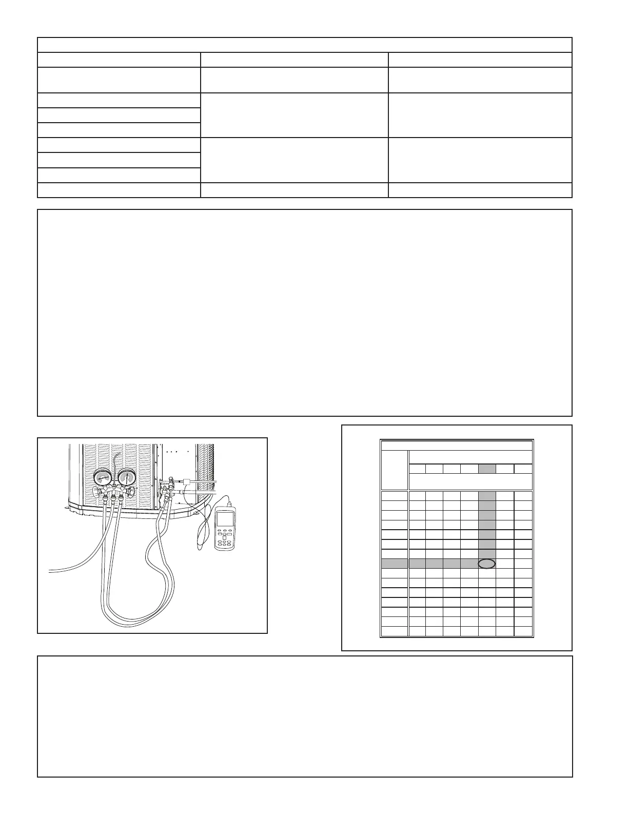
1. Connect gages to refrigerant bottle and unit as illustrated.
2. Purge all hoses.
3. Open bottle.
4. Stop adding refrigerant when liquid line temperature and Liquid Gage Pressure matches the charging chart
Final Subcooling value.
Recover refrigerant if the Liquid Gage Pressure is higher than the chart value.