EasyManua.ls Logo

Trane 4TWX8 User Manual

Trane 4TWX8
24 pages
To Next Page IconTo Next Page
Page #1 background imageLoading...
Page #1 background image
18-BC91D1-6B-EN
ALL phases of this installation must comply with NATIONAL, STATE AND LOCAL CODES
IMPORTANT — This Document is customer property and is to remain with this unit. Please return to service informa-
tion pack upon completion of work.
Condensing Units
These instructions do not cover all variations in systems or provide for every possible contingency to be met in connection with
the installation. Should further information be desired or should particular problems arise which are not covered sufficiently for the
purchaser’s purposes, the matter should be referred to your installing dealer or local distributor.
Note: The manufacturer recommends installing only approved matched indoor and outdoor systems. All of the manufacture’s split
systems are AHRI rated only with TXV/EEV indoor systems. Some of the benefits of installing approved matched indoor and out-
door split systems are maximum efficiency, optimum performance and the best overall system reliability.
4TWX8
Installer’s Guide
Table of Contents
Section 1. Safety ..................................................................................... 2
Section 2. Unit Location Considerations ............................................. 3
Section 3. Unit Preparation.................................................................... 5
Section 4. Setting the Unit ..................................................................... 5
Section 5. Refrigerant Line Considerations ......................................... 6
Section 6. Refrigerant Line Routing ..................................................... 8
Section 7. Refrigerant Line Brazing ...................................................... 9
Section 8. Refrigerant Line Leak Check ............................................. 11
Section 9. Evacuation .......................................................................... 12
Section 10. Service Valves .................................................................. 12
Section 11. Electrical - Low Voltage ................................................... 13
Section 12. Electrical - High Voltage .................................................. 15
Section 13. Start Up.............................................................................. 16
Section 14. System Charge Adjustment............................................. 17
Section 15. Checkout Procedures and Troubleshooting .................. 23
Question and Answer IconNeed help?

Do you have a question about the Trane 4TWX8 and is the answer not in the manual?

Trane 4TWX8 Specifications

General IconGeneral
Model Number4TWX8
CategoryHeat Pump
HSPF RatingUp to 10
RefrigerantR-410A
Warranty10 year limited warranty on compressor

Summary

Section 1: Safety

Section 2: Unit Location Considerations

Unit Dimensions and Weight

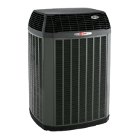
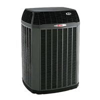
Details the physical dimensions and estimated weights for different condensing unit models.

Refrigerant Piping Limits

Specifies maximum total length and vertical change allowed for refrigerant lines.

Suggested Locations for Best Reliability

Provides guidance on unit placement for optimal airflow, noise reduction, and avoiding weather impacts.

Cold Climate Considerations

Recommends precautions for units installed in areas with snow and freezing temperatures.

Coastal Considerations

Advises on protective measures for units installed near salt water environments.

Section 3: Unit Preparation

Prepare The Unit For Installation

Outlines steps to check for damage and safely remove the unit from its pallet.

Section 4: Setting the Unit

Pad Installation

Details requirements for installing the unit on a support pad, including size, levelness, and code compliance.

Section 5: Refrigerant Line Considerations

Refrigerant Line and Service Valve Connection Sizes

Presents a table specifying line sizes and service valve connection sizes for different models.

Factory Charge

Explains the factory charge for the condensing unit and connecting lines, emphasizing verification.

Required Refrigerant Line Length

Instructs on determining the required total line length and vertical change for system configuration.

Refrigerant Line Insulation

Emphasizes the importance of insulating the vapor line and preventing contact between lines.

Reuse Existing Refrigerant Lines

Provides precautions for using existing refrigerant lines, focusing on brazing and line condition.

Section 6: Refrigerant Line Routing

Precautions

Details best practices for routing refrigerant lines to prevent noise and ensure proper installation.

Section 7: Refrigerant Line Brazing

Braze The Refrigerant Lines

Provides a step-by-step guide for the proper brazing process of refrigerant lines.

Section 8: Refrigerant Line Leak Check

Check For Leaks

Details the procedure for pressurizing lines with nitrogen and checking for leaks using soapy solution.

Section 9: Evacuation

Evacuate the Refrigerant Lines and Indoor Coil

Explains the process of evacuating the system to a specific micron level using a vacuum pump and micron gauge.

Section 10: Service Valves

Open the Gas Service Valve

Guides on how to properly open the gas service valve after leak check and evacuation.

Open the Liquid Service Valve

Provides instructions and warnings for opening the liquid service valve, emphasizing caution.

Section 11: Electrical - Low Voltage

Low Voltage Maximum Wire Length

Presents a table defining maximum lengths for low voltage wiring based on wire gauge.

Low Voltage Hook-up Diagrams

Illustrates wiring connections for thermostats, air handlers, and outdoor units for different control systems.

Defrost Control

Explains the defrost control settings, termination temperatures, and checkout procedures.

Section 12: Electrical - High Voltage

High Voltage Power Supply

Emphasizes ensuring high voltage power supply matches equipment nameplate and complies with codes.

High Voltage Disconnect Switch

Recommends installing a separate disconnect switch and using flexible conduit for high voltage connections.

High Voltage Ground

States the requirement to ground the outdoor unit according to national, state, and local codes.

Section 13: Start Up

System Start Up

Details the step-by-step procedure for safely starting up the installed system, including waiting periods.

Section 14: System Charge Adjustment

Temperature Measurements

Explains the necessity of measuring outdoor and indoor temperatures for accurate system charging.

Subcooling Charging in Cooling (Above 55° F Outdoor Temp.)

Provides charts and steps for adjusting system charge using subcooling for outdoor temps above 55°F.

Subcooling Charging Below 55° F Outdoor Temp. (In Heating Only)

Recommends weighing the charge in heating mode for outdoor temps below 55°F, referencing pressure curves.

Section 15: Checkout Procedures and Troubleshooting

Operational And Checkout Procedures

Lists essential checks and procedures to ensure proper system operation and performance post-installation.

Troubleshooting

Offers a fault guide correlating system faults with potential causes for refrigerant and electrical issues.

Related product manuals