Do you have a question about the Trane 4WCZ6036B3000A and is the answer not in the manual?
Details hazardous voltage, electrical hazards, grounding, R-410A refrigerant safety, and panel installation precautions.
Overview of the manual, unit installation guidelines, and Underwriters Laboratory listing.
Procedures for checking the unit for damage after unloading and reporting issues.
Presents detailed technical specifications for various unit models, including performance and electrical data.
Process for charging the unit in cooling mode when outdoor temp is above 55°F, using subcooling.
Recommended method for charging in heating mode when outdoor temp is below 55°F.
Recommended service clearances for unit installation, specified by tonnage and economizer presence.
Minimum clearances required between the unit and combustible surfaces for safety.
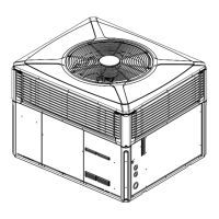
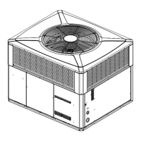
Lists physical dimensions for different unit models in millimeters and inches, with diagrams.
Provides corner weights, shipping weight, unit weight, and center of gravity for various unit models.
Guidelines for unit location, service clearance, and avoiding contamination for horizontal airflow.
Recommendations for unit placement, roof curb installation, and structural support for down airflow.
Instructions for placing and securing the unit on a pad for ground-level installations, including clearance.
Steps for converting airflow direction and installing roof mounting curbs prior to unit placement.
Critical safety warnings and procedures for safely lifting and rigging the unit, including test lifting.
Guidance on positioning and lowering the unit onto the mounting curb, ensuring proper fit and stability.
Procedure for installing the unit on a fabricated frame or channel iron support on the roof.
Instructions for installing the unit on sleeper rails directly on the roof structure.
Detailed measurements and diagrams for field-fabricated roof curbs to ensure proper unit fit.
Illustrates a typical rooftop installation of the unit with horizontal airflow using a frame.
Illustrates a typical rooftop installation of the unit with down airflow using a frame.
Guides for attaching ductwork to curbs, frames, and the unit, emphasizing flexible connections.
Instructions for installing the condensate drain connection, including trap requirements and proper pitching.
Information on installing air filters, including accessory filter racks and filter size recommendations.
Details on power supply requirements, disconnect switch installation, over current protection, and conduit.
Step-by-step instructions for making high voltage connections to contactors and grounding the unit.
Guidelines for routing low voltage control wiring, avoiding power wiring, and preventing shorts.
Recommendations for thermostat wire size and maximum length to ensure proper voltage drop.
A comprehensive checklist to ensure all installation steps are completed correctly before unit startup.
Instructions for starting and shutting down the unit in both cooling and heating modes.
Procedures for checking operating pressures and verifying supply voltage during unit operation.
Describes the unit's operation during cooling cycles, including 1st and 2nd stage cooling.
Explains the unit's operation during heating cycles, including 1st and 2nd stage heating.
Explains how the demand defrost control removes frost from the outdoor coil during heating cycles.
Details on adjusting blower speed using dip switches on the ECM Fan Control for optimal airflow.
Checklist of essential inspections to perform after installation is complete for proper operation.
Guidance for routine maintenance tasks for optimal unit performance and longevity.
Information on identifying unit faults via flashing lights and PIN identification for diagnostics.
A diagnostic table to identify and resolve issues related to the demand defrost control system.
Further diagnostic steps and actions for various symptoms related to the defrost control system.
Graphical representation of discharge/suction pressures for cooling mode vs. outdoor temp and airflow.
Graphical representation of discharge/suction pressures for heating mode vs. outdoor temp and airflow.
Graphical representation of discharge/suction pressures for cooling mode vs. outdoor temp and airflow.
Graphical representation of discharge/suction pressures for heating mode vs. outdoor temp and airflow.
Graphical representation of discharge/suction pressures for cooling mode vs. outdoor temp and airflow.
Graphical representation of discharge/suction pressures for heating mode vs. outdoor temp and airflow.
Data correlating static pressure with airflow (CFM) for different models and speeds.
Nominal airflow capacities for various switch settings when auxiliary heat is engaged.
Diagram illustrating the refrigerant flow path during the heating cycle.
Diagram illustrating the refrigerant flow path during the cooling cycle.
Matrix correlating system faults with their primary and secondary causes for diagnosis.
Guidance on troubleshooting common issues before calling for service and contact information.
| Model Number | 4WCZ6036B3000A |
|---|---|
| Category | Heat Pump |
| Cooling Capacity | 36000 BTU/H |
| SEER Rating | 16 |
| Refrigerant Type | R-410A |
| Voltage | 208/230 V |
| Phase | 1 |
| Sound Level (Outdoor Unit) | 72 dB |
| Compressor Type | Scroll |