11
• An electrical disconnect must be located within sight
of and readily accessible to the unit. This switch shall be
capable of electrically de-energizing the outdoor unit. See
unit data label for proper incoming field wiring. Any other
wiring methods must be acceptable to authority having
jurisdiction.
• Use only copper wire for the line voltage power supply to
this unit as shown in
Table 2. Use proper code agency listed
conduit and a conduit connector for connecting the supply
wires to the unit. Use of rain tight conduit is recommended.
• Provide power supply for the unit in accordance with the
unit wiring diagram and the unit rating plate.
• Overcurrent protection must be provided at the branch circuit
distribution panel and sized as shown on the unit rating
label and according to applicable local codes. See
Table
10 (or the unit rating plate) for minimum circuit ampacity
and maximum overcurrent protection limits.
• A wiring diagram is located on the inside cover of the control
access panel of the outdoor unit. The installer should become
familiar with the wiring diagram before making any electrical
connections to the outdoor unit. See
Figure 12 and Figure
13.
• Units are shipped from the factory wired for 230 volt
transformer operation.
• Connect the line-voltage leads to the terminals on the
contactor inside the control compartment.
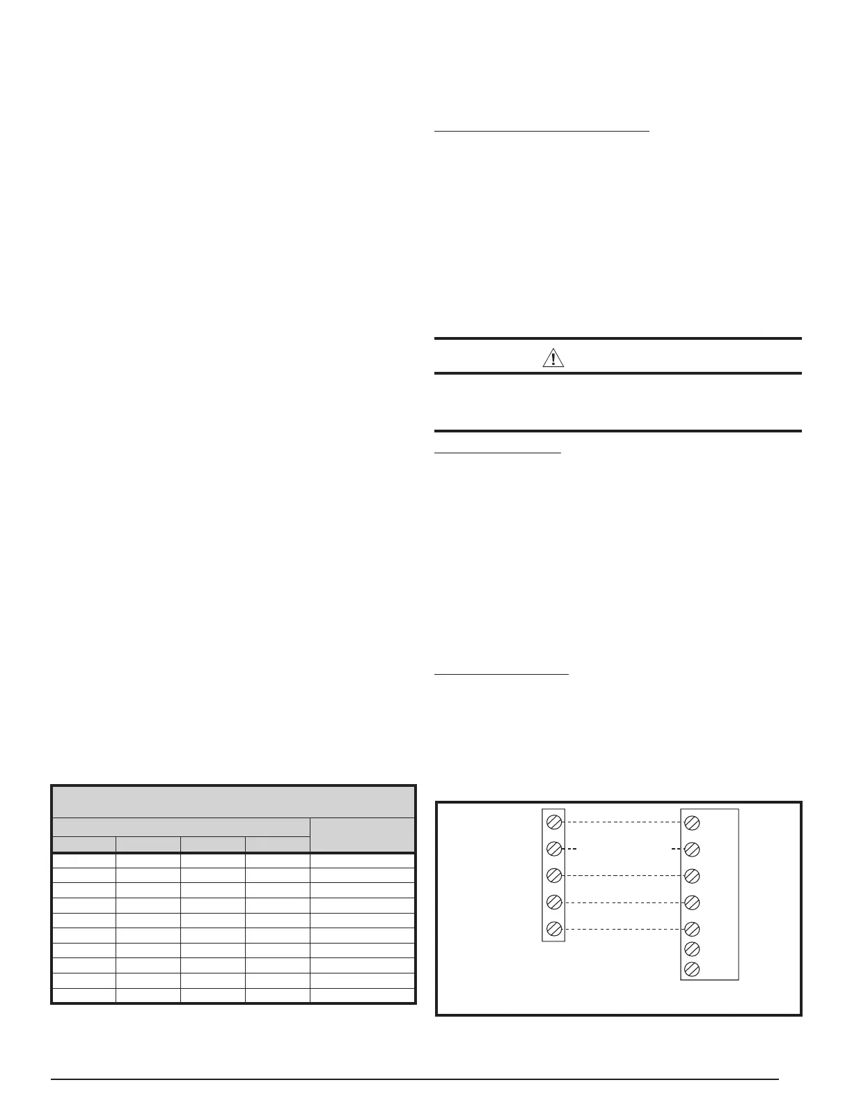
Thermostat / Low Voltage Connections
• This unit is designed to operate from a 24 VAC Class II
control circuit. A single stage cooling / single stage heating
thermostat should be used with this unit. See
Figure 6 (page
11)
for typical thermostat connection.
• The control circuit wiring must comply with the current
provisions of the NEC (ANSI/NFPA 70) and with applicable
local codes having jurisdiction. Thermostat connections
should be made in accordance with the instructions supplied
with the thermostat and the indoor equipment.
• The low voltage wires must be properly connected. Route
24V control wires through the sealing grommet near the
power entrance.
• Several thermostat options are available depending on the
accessories installed with the unit. Select a thermostat that
operates in conjunction with the installed accessories.
• The thermostat should be mounted about 5 feet above the
floor on an inside wall. DO NOT install the thermostat on
an outside wall or any other location where its operation
may be adversely affected by radiant heat from fireplaces,
sunlight, or lighting fixtures, and convective heat from warm
air registers or electrical appliances. Refer to the thermostat
manufacturer’s instruction sheet for detailed mounting
information.
Checking Heat Anticipator Settings
• Add the current draw of the system heating components.
OR
• Measure the current flow on the thermostat R-W circuit
after the circulating blower motor has started. Set the heat
anticipator according to the thermostat manufacturer’s
instructions for heat anticipator settings.
Blower Speed
The blower speed is preset at the factory for fan only, heating,
and cooling operation. These factory settings are listed in
Table 6 (page 19) and Table 7 (page 20). For optimum system
performance and comfort, it may be necessary to change the
factory set speed.
CAUTION:
To avoid personal injury or property damage, make
sure the motor leads do not come into contact with
any uninsulated metal components of the unit.
5-Speed ECM Motor
• Shut off all electrical power to the unit and remove the
control panel. NOTE: The furnace board has slide switches
to select between blower speeds that are preset from the
factory. The heat, cool, and fan speed can be changes by
sliding the switch from the available options of L-Low. ML-
Medium Low, MH-Medium High, H-High. The blower motor
speeds increase as the switch is moved from Low to High.
• A movable jumper beside the blower speed slide switches
change fan speed(G call). The fan speed is preset from
the factory for the Lowest blower speed L. Changing this
position of the jumper one setting at a time will increase the
fan speed.
Optional Furnace Control Board Connections
Electronic Air Cleaner
The furnace control board provides output terminals for an
optional electronic air cleaner (EAC) that can be installed in the
return air duct of your system. THE EAC output is energized
any time the HEAT or COOL blower speed is energized.
Control ratings are 1.0 Amp. @ 240 VAC. Output connections
are made via board terminals labeled EAC and NEUTRAL.
COPPER WIRE SIZE — AWG
(1% VOLTAGE DROP)
SUPPLY WIRE LENGTH-FEET
SUPPLY CIRCUIT
AMPACITY
200 150 100 50
6 8 10 14 15
46812 20
46810 25
44610 30
3468 35
3468 40
2346 45
2346 50
2346 55
1234 60
NOTE: Wire Size based on N.E.C. for 60° type copper conductors.
Table 2. Copper Wire Size
Figure 6. Typical Thermostat Connection
(Field Supplied) for 1-Stage Cool / 1-Stage Heat
C
Y1
R
G
W1
R
C
Y
G
W1
Y2
TERMINAL BLOCK
FURNACE
BOARD
Optional, Refer to
Thermostat Instructions
INDOOR THERMOSTAT
SUB-BASE (TYPICAL)
A1


 To Next Page