18-AD48D1-1A-EN 5
Installer’s Guide
D. RECOMMENDATION
If a coil is part of the total system installation, use the Installer’s
Guide packaged with the furnaces, outdoor sections, and
thermostat for physically installing those components.
E. FURNACE IN UPFLOW POSITION:
IMPORTANT: Only upow/downow coils may be installed in
the upow position -
5PXCA001AS3HAA, 5PXCA002AS3HAA,
5PXCB003AS3HAA, 5PXCB004AS3HAA,
5PXCC005AS3HAA, 5PXCB006AS3HAA,
5PXCC007AS3HAA, 5PXCD008AS3HAA,
5PXCC009AS3HAA, 5PXCD010AS3HAA
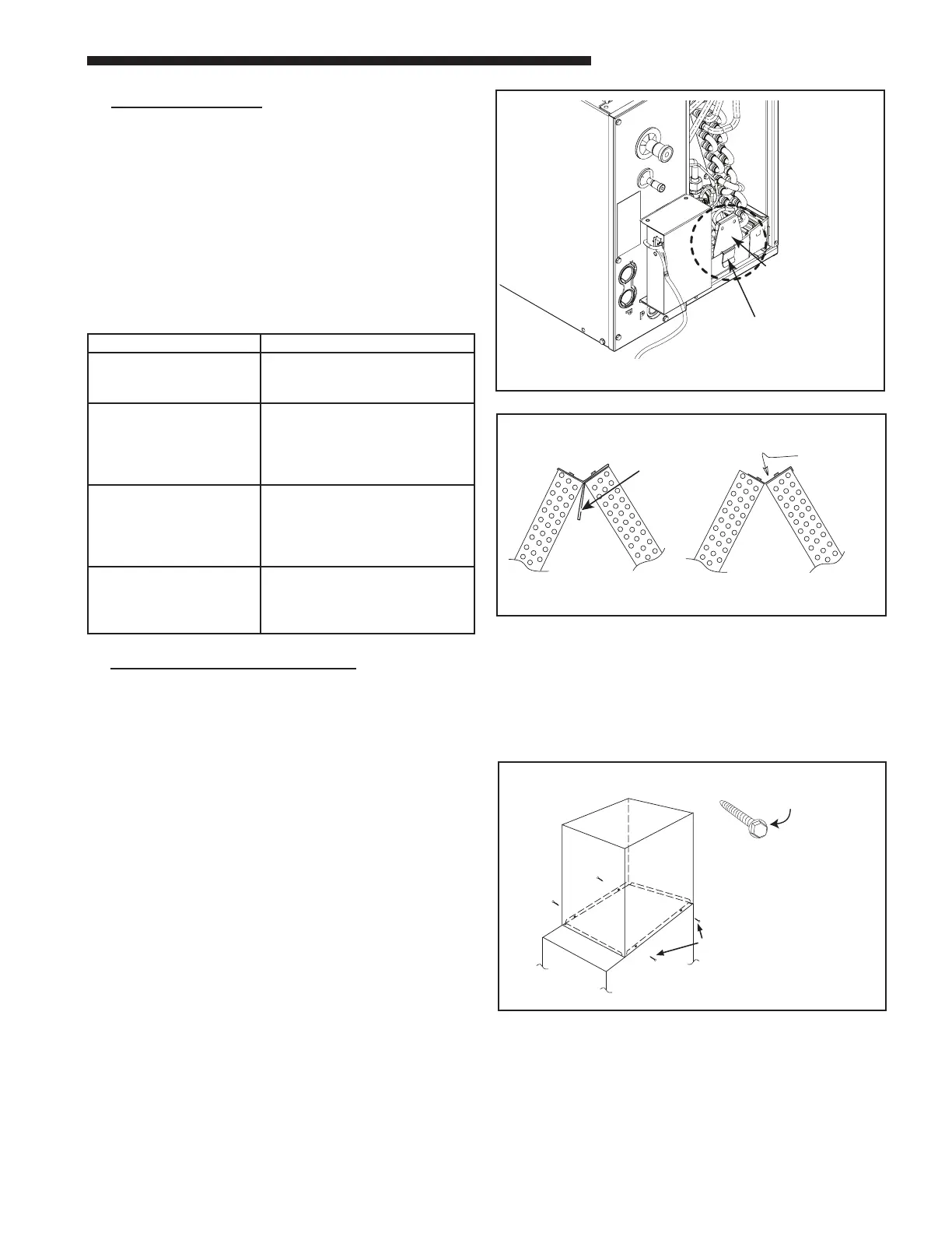
1. UPFLOW COIL CONVERSION: Ensure the refrigerant
sensor is attached to the primary pan per Figure 2.
The sensor should face inward toward the coil and may
be positioned anywhere of the front lip of the pan. Ensure
the mounting bracket is seated as far down on the pan as
possible.
2. EFFICIENCY OPTIONS FOR UPFLOW INSTALLATIONS:
While not required, optional removal of some coil
components will maximize airow eciency.
a. Remove the coil by sliding the coil out of the enclosure.
b. On models 5TXCC005, 5TXCB006, 5TXCC007,
5TXCD008, and 5TXCC009 only, remove the factory
installed two-piece bae assembly from the top of
the coil by removing the 5/16" hex head screws and
discard the inner water management bae. See Figure
3. Replace only the top bae using the same screws
previously provided.
c. On model 5TXCC009 only, remove the two outer water
management baes by removing the 5/16" hex screws
and discard. See gure 7.
Model Number Horizontal Kit No.
5PXCA001AS3HAA
5PXCB003AS3HAA
5PXCBD03AS3HDA
BAYCONV18B
5PXCA002AS3HAA
5PXCB004AS3HAA
5PXCC005AS3HAA
5PXCBD04AS3HDA
5PXCCD05AS3HDA
BAYCONV23B
5PXCB006AS3HAA
5PXCC007AS3HAA
5PXCD008AS3HAA
5PXCBD06AS3HDA
5PXCCD07AS3HDA
BAYCONV27B
5PXCC009AS3HAA
5PXCD010AS3HAA
5PXCCD09AS3HDA
5PXCDD10AS3HDA
BAYCONV30C
1-1/2” MAXIMUM
FIELD SUPPLIED
UPFLOW
FURNACE
CASED
COIL
SCREWS
(BO
FOR UPFLOW
INSTALLATIONS
Figure 4
Figure 3
Note: 5PXC upow coils may be installed in Upow,
Downow, Horizontal Right with kit, and Horizontal Left with
kit. 5PXC downow coils may be installed in Downow and
Horizontal Right with kit.
Important: If installing the coil in the horizontal position, you
MUST use the horizontal kit listed below for this coil model
number and follow the instructions in the installation guide
provided with the conversion kit.
Refrigerant Sensor
should be seated
fully on pan
Dimension from the bottom of
the Drain Pan to the bottom of
the Sensor should be 0.8" max
Figure 2
3. UPFLOW GAS FURNACE:
a. Apply gasket material (duct seal eld supplied) to ALL
mating surfaces between the furnace and the coil case.
b. Set the coil case on top of the furnace. Connect the
furnace and ductwork to the coil case using eld
supplied screws. See Figure 4.
c. Seal for air leaks as required.




 To Next Page