18-AC128D1-1B-EN 9
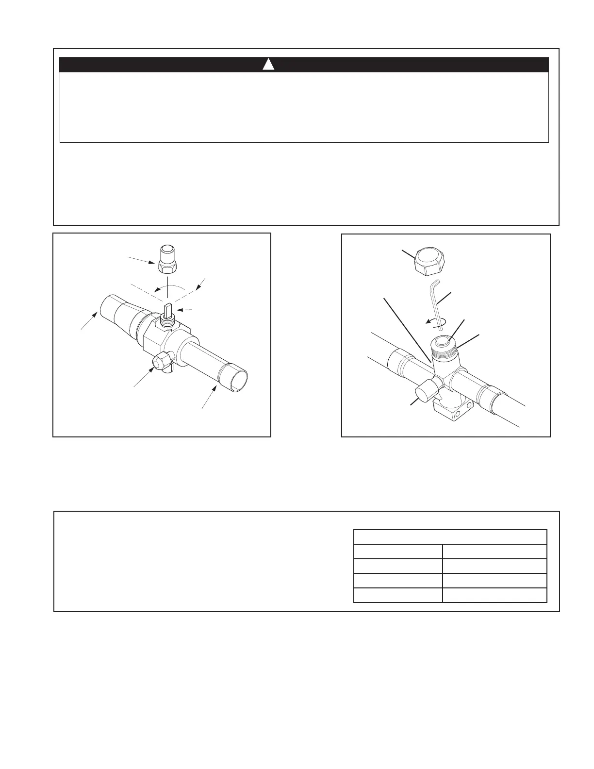
10.2 Open the Liquid Service Valve
Important: Leak check and evacuation must be completed before opening the service valves.
STEP 1 - Remove service valve cap.
STEP 2 - Fully insert 3/16” hex wrench into the stem and back out counterclockwise until valve stem just touches
the rolled edge (approximately five (5) turns.)
STEP 3 - Replace the valve cap to prevent leaks. Tighten finger tight plus an additional 1/6 turn.
SERVICE VALVES!
Failure to follow this warning will result in abrupt
release of system charge and may result in personal injury and/or property damage. Extreme caution should be
exercised when opening the Suction and Liquid Line Service Valve. Turn valve stem counterclockwise only until
the stem contacts the rolled edge. No torque is required.
WARNING
!
CAP
1/4 TURN ONLY
COUNTERCLOCKWISE
FOR FULL OPEN
POSITION
VALVE STEM
GAS LINE CONNECTION
UNIT SIDE
OF VALVE
PRESSURE TAP PORT
Gas Service Valve Liquid Service Valve
Cap
Rolled Edge to
Captivate Stem
Hex Headed
Valve System
Service Port
3/16” Hex Wrench
Unit Side
of Service
Valve
Section 11. Electrical - Low Voltage
11.1 Low Voltage Maximum Wire Length
Table 11.1 defines the maximum total length of
low voltage wiring from the outdoor unit, to the
indoor unit, and to the thermostat.
Table 11.1
24 VOLTS
WIRE SIZE MAX. WIRE LENGTH
18 AWG 150 Ft.
16 AWG 225 Ft.
14 AWG 300 Ft.