EasyManua.ls Logo

Trane 5TTR3018-060 - User Manual

Trane 5TTR3018-060
28 pages
Print Icon
To Next Page IconTo Next Page
Loading...
18-AC127D1-1A-EN
ALL phases of this installation must comply with NATIONAL, STATE AND LOCAL CODES
IMPORTANTThis Document is customer property and is to remain with this unit. Please return to service informa-
tion pack upon completion of work.
Condensing Units
These instructions do not cover all variations in systems or provide for every possible contingency to be met in connection with
the installation. Should further information be desired or should particular problems arise which are not covered sufficiently for the
purchaser’s purposes, the matter should be referred to your installing dealer or local distributor.
Note: The manufacturer recommends installing only approved matched indoor and outdoor systems. Some of the benefits of
installing approved matched indoor and outdoor split systems are maximum efficiency, optimum performance and the best overall
system reliability.
5TTR3018 – 060
Installation and Operation Manual
Table of Contents
Section 1. Safety ..................................................................................... 2
Section 2. Unit Location Considerations ............................................. 3
Section 3. Unit Preparation.................................................................... 4
Section 4. Setting the Unit ..................................................................... 5
Section 5. Refrigerant Line Considerations ......................................... 5
Section 6. Refrigerant Line Routing ..................................................... 6
Section 7. Refrigerant Line Brazing ...................................................... 7
Section 8. Refrigerant Line Leak Check ............................................... 9
Section 9. Evacuation .......................................................................... 10
Section 10. Service Valves .................................................................. 10
Section 11. Electrical - Low Voltage ................................................... 11
Section 12. Electrical - High Voltage .................................................. 12
Section 13. Start Up.............................................................................. 13
Section 14. System Charge Adjustment............................................. 14
Section 15. Checkout Procedures ...................................................... 19
Section 16. Refrigeration Circuits........................................................20
Section 17. Wiring Diagrams................................................................22
Section 18. Pressure Curves................................................................26
Question and Answer IconNeed help?

Do you have a question about the Trane 5TTR3018-060 and is the answer not in the manual?

Overview

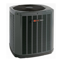
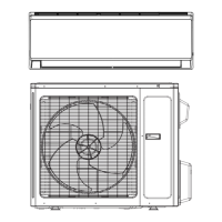
This document provides a comprehensive manual for Trane's 5TTR3018 – 060 series of condensing units, designed for residential and commercial applications. These units are part of a complete heating, ventilating, and air-conditioning (HVAC) system, working in conjunction with an indoor evaporator coil and air handler to provide cooling.

Function Description

The Trane condensing units are designed to extract heat from an indoor space and dissipate it outdoors, thereby cooling the indoor environment. They achieve this by circulating refrigerant between the indoor and outdoor units. The compressor in the condensing unit pressurizes the refrigerant, which then flows through the outdoor coil, releasing heat to the ambient air. The cooled refrigerant then travels to the indoor evaporator coil, where it absorbs heat from the indoor air, providing cooling. This cycle repeats continuously to maintain the desired indoor temperature. The units are designed for optimal performance when matched with approved indoor units and properly sized refrigerant lines.

Important Technical Specifications

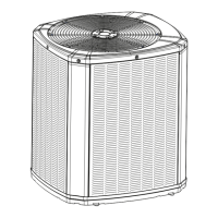
The manual provides detailed specifications for various models within the 5TTR3018 – 060 series, including dimensions, weight, and refrigerant piping limits.

Unit Dimensions and Weight (Table 2.1):

  • 5TTR3018A: 29 x 26 x 29 inches (H x D x W), 133 lbs.
  • 5TTR3024A: 29 x 30 x 33 inches (H x D x W), 161 lbs.
  • 5TTR3030A: 29 x 30 x 33 inches (H x D x W), 161 lbs.
  • 5TTR3042A: 37 x 30 x 33 inches (H x D x W), 184 lbs.
  • 5TTR3048A: 37 x 34 x 37 inches (H x D x W), 211 lbs.
  • 5TTR3060A: 37 x 34 x 37 inches (H x D x W), 211 lbs.

Refrigerant Piping Limits:

  • Maximum TOTAL length of refrigerant lines from outdoor to indoor unit: 150 feet (including lift).
  • Maximum vertical change: 50 feet.
  • Service valve connection diameters vary by model, as detailed in Table 5.1. For instance, models like 5TTR3018A use 3/8" liquid and 3/4" vapor lines, while larger models like 5TTR3060A use 3/8" liquid and 7/8" vapor lines.

Electrical Specifications (Table 11.1):

  • 24 Volts Wiring:
    • 18 AWG: 150 Ft. Max. Wire Length
    • 16 AWG: 225 Ft. Max. Wire Length
    • 14 AWG: 300 Ft. Max. Wire Length

Refrigerant Type: The units use R-454B refrigerant, which is a flammable refrigerant. Specific warnings and precautions related to handling this refrigerant are provided throughout the manual.

Usage Features

The manual outlines various features related to the installation, operation, and maintenance of the condensing units.

Installation:

  • Pad Installation: The unit must be installed on a support pad (e.g., concrete slab) that is level, separate from any structure, and provides proper drainage. The pad must be at least 1" larger than the unit on all sides.
  • Location Considerations:
    • Ensure top discharge area is unrestricted for at least five (5) feet above the unit.
    • Maintain three (3) feet clearance from the control box (access panels) and any other side requiring service.
    • Avoid locating close to bedrooms as operational sounds may be objectionable.
    • Position the outdoor unit a minimum of 12" from any wall or surrounding shrubbery to ensure adequate airflow.
    • Outdoor unit location must be far enough away from any structure to prevent excess roof runoff water from pouring directly on the unit.
  • Refrigerant Line Routing: Secure vapor and liquid lines from joists using isolators every 8 ft. or appropriate method. Avoid hanging line sets from ductwork. Ensure proper insulation of all refrigerant lines.
  • Brazing: Follow specific steps for brazing refrigerant lines, including deburring pipes, removing pressure tap caps, purging with dry nitrogen, wrapping a wet rag around the valve body to prevent heat damage, and installing a liquid line filter/drier.
  • Leak Check: After brazing, perform a leak check by pressurizing the refrigerant lines and evaporator coil to 150 PSIG using dry nitrogen. Check for leaks using a soapy solution or bubbles at each brazed location.
  • Evacuation: Evacuate the unit until the micron gauge reads no higher than 350 microns, then close off the valve to the vacuum pump.
  • Service Valves: The manual details how to open and close both the gas and liquid service valves, emphasizing the importance of turning them counterclockwise to the fully open position.
  • Electrical Wiring: Provides diagrams for low voltage hook-up (24 VAC) for various thermostat and air handler configurations (with and without furnace, with variable speed furnace). High voltage wiring requires a separate disconnect switch and proper grounding.

System Start-Up:

  • Ensure Sections 7 through 12 (Brazing, Leak Check, Evacuation, Service Valves, Electrical, High Voltage) have been completed.
  • Set the system thermostat to OFF.
  • Turn on disconnect(s) to apply power to the indoor and outdoor units.
  • Wait one (1) hour before starting the unit if the compressor crankcase heater accessory is used and the Outdoor Ambient is below 70°F.
  • Set the system thermostat to ON.

System Charge Adjustment:

  • Installer must mark the total refrigerant charge on the outdoor unit label after adjusting for indoor coil and lineset.
  • Technicians must have their refrigerant cylinder on a scale during the charging procedure.
  • Use subcooling method for charging. The manual provides detailed steps and tables (Table 14.2) for determining the proper liquid gauge pressure based on liquid line temperature and final subcooling target.
  • Subcooling (in cooling mode): The recommended method of charging above 55°F ambient outdoor temperature.
  • Weigh-In Method: Can be used for initial installation, or when replacement power is not available or when the desired temperatures for the standard charging method are outside normal bounds.
  • Fixed Orifice Superheat Charging Table: Provided for specific indoor wet bulb temperatures and outdoor dry bulb temperatures.

Maintenance Features

The manual emphasizes the importance of proper installation and regular checks to ensure the longevity and efficient operation of the condensing unit.

General Maintenance:

  • Checklist Procedures: A comprehensive checklist is provided for final installation and unit operational checks, covering refrigerant lines, insulation, electrical connections, fan operation, and overall system safety.
  • Refrigerant Detection System: The approved indoor/outdoor combination will provide sufficient safe ventilation. Airflow is sufficient to cover minimum room area including adjustments for altitude. All systems require a refrigerant detection system so no altitude adjustment factors are required. Installers must ensure the refrigerant detection system is connected and placed in appropriate orientation per application. The control system power shall not be interrupted to ensure the refrigerant detection system is always functioning.
  • Refrigerant Line Maintenance: Regular inspection of refrigerant lines for leaks, damage, and proper insulation is crucial. Ensure all joints are brazed, not soldered.
  • Reuse Existing Refrigerant Lines: For retrofit applications, where existing indoor evaporator coil and/or refrigerant lines will be reused, ensure that the indoor evaporator coil and refrigerant lines are the correct size, that refrigerant lines are free of leaks, acid, and oil.
  • Pressure Curves: The manual includes pressure curves (Liquid Pressure vs. Outdoor Temperature and Suction Pressure vs. Outdoor Temperature) for various models, which are essential for diagnosing system performance and ensuring proper charge.

Safety Warnings: The manual is replete with safety warnings, highlighting potential hazards such as:

  • Electrical Shock: Always disconnect power before servicing.
  • Fire/Explosion: Due to flammable refrigerant (R-454B), avoid open flames and ensure proper ventilation.
  • Personal Injury: Wear appropriate personal protective equipment (PPE) and follow safe work practices.
  • Property Damage: Improper installation or maintenance can lead to equipment failure and property damage.
  • Chemical Exposure: R-454B refrigerant can cause chemical burns and other reproductive harm. Refer to www.P65Warnings.ca.gov for more information.
  • Hot Surfaces: Scroll compressor dome temperatures may be hot, causing minor to severe burning.

Overall, this manual serves as a critical resource for installers, technicians, and owners of Trane's 5TTR3018 – 060 condensing units, providing detailed instructions for safe and efficient operation and maintenance.

Trane 5TTR3018-060 Specifications

General IconGeneral
BrandTrane
Model5TTR3018-060
CategoryHeat Pump
LanguageEnglish

Related product manuals