EasyManua.ls Logo

Trane 5TTR4018A - User Manual

Trane 5TTR4018A
26 pages
Print Icon
To Next Page IconTo Next Page
Loading...
18-AC128D1-1B-EN
ALL phases of this installation must comply with NATIONAL, STATE AND LOCAL CODES
IMPORTANTThis Document is customer property and is to remain with this unit. Please return to service informa-
tion pack upon completion of work.
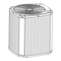
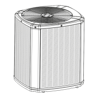
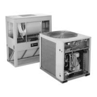
Condensing Units
These instructions do not cover all variations in systems or provide for every possible contingency to be met in connection with
the installation. Should further information be desired or should particular problems arise which are not covered sufficiently for the
purchaser’s purposes, the matter should be referred to your installing dealer or local distributor.
Note: The manufacturer recommends installing only approved matched indoor and outdoor systems. Some of the benefits of
installing approved matched indoor and outdoor split systems are maximum efficiency, optimum performance and the best overall
system reliability.
5TTR4018 – 060
Installation and Operation Manual
Table of Contents
Section 1. Safety ..................................................................................... 2
Section 2. Unit Location Considerations.............................................. 3
Section 3. Unit Preparation .................................................................... 4
Section 4. Setting the Unit ..................................................................... 4
Section 5. Refrigerant Line Considerations ......................................... 4
Section 6. Refrigerant Line Routing ..................................................... 5
Section 7. Refrigerant Line Brazing ...................................................... 7
Section 8. Refrigerant Line Leak Check ............................................... 8
Section 9. Evacuation ............................................................................. 8
Section 10. Service Valves ..................................................................... 8
Section 11. Electrical - Low Voltage ..................................................... 9
Section 12. Electrical - High Voltage .................................................. 11
Section 13. Start Up .............................................................................. 11
Section 14. System Charge Adjustment ............................................. 12
Section 15. Checkout Procedures ....................................................... 16
Section 16. Refrigeration Circuits........................................................18
Section 17. Wiring Diagrams................................................................20
Section 18. Pressure Curves................................................................23
Note: R-454B refrigerant is an “A2L refrigerant meaning: A = non-toxic, 2 = flammable, L = low burning velocity.
The term “A2L is used throughout this document.
Question and Answer IconNeed help?

Do you have a question about the Trane 5TTR4018A and is the answer not in the manual?

Overview

This document is an Installation and Operation Manual for Trane Condensing Units, specifically models 5TTR4018 – 060. These units are designed for use in heating, ventilating, and air-conditioning (HVAC) systems. The manual provides comprehensive instructions for the safe and proper installation, startup, and maintenance of these condensing units.

Function Description:

The Trane Condensing Units are outdoor components of a split HVAC system. They work in conjunction with an indoor evaporator coil and refrigerant lines to provide cooling. The condensing unit compresses and condenses refrigerant, releasing heat to the outdoor air, which is then circulated back to the indoor unit to absorb heat from the indoor environment. These units utilize R-454B refrigerant, which is classified as an "A2L" refrigerant, meaning it is non-toxic and has a low burning velocity.

Important Technical Specifications:

  • Models Covered: 5TTR4018A, 5TTR4024A, 5TTR4030A, 5TTR4036A, 5TTR4042A, 5TTR4048A, 5TTR4060A.
  • Cooling Capacity: 1.5 - 5 Ton (as indicated in the operating range table).
  • Operating Range (Cooling): 55°F - 120°F outdoor temperature.
  • Refrigerant Type: R-454B (A2L refrigerant).
  • Refrigerant Piping Limits:
    • Maximum TOTAL length of refrigerant lines (outdoor to indoor unit): 150 feet (including lift).
    • Maximum vertical change (lift): 50 feet.
    • Service valve connection diameters vary by model (e.g., 5TTR4018A: Vapor Line 3/4", Liquid Line 5/16"; 5TTR4060A: Vapor Line 1-1/8", Liquid Line 5/16").
  • Unit Dimensions and Weight: Vary by model. For instance, the 5TTR4018A is 37 x 30 x 33 inches (H x D x W) and weighs 184 lbs, while the 5TTR4060A is 45 x 34 x 37 inches and weighs 252 lbs.
  • Low Voltage Wiring: Maximum wire lengths are specified based on AWG (e.g., 18 AWG for 150 ft, 14 AWG for 300 ft).
  • Charging Method: Subcooling charging (above 55°F outdoor temperature) is the primary method, with a weigh-in method available for initial installation or when conditions are outside the subcooling range.
  • Pressure Curves: Detailed pressure curves are provided for various models (5TTR4018A, 5TTR4024A, 5TTR4030A, 5TTR4036A, 5TTR4042A, 5TTR4048A, 5TTR4060A) to verify typical performance during cooling operations at different outdoor temperatures and indoor wet bulb temperatures.

Usage Features:

  • Matched Systems: The manufacturer recommends installing only approved matched indoor and outdoor systems for maximum efficiency, optimum performance, and best overall system reliability.
  • Location Considerations:
    • Ensure the top discharge area is unrestricted for at least five feet above the unit.
    • Provide three feet clearance in front of the control box and any other side requiring service.
    • Maintain a minimum of 12 inches from any wall or surrounding shrubbery for adequate airflow.
    • Avoid locating near bedrooms due to potential operational sounds.
    • Prevent excess roof runoff water from pouring directly on the unit.
  • Refrigerant Line Installation:
    • Vapor Line must always be insulated.
    • Liquid Line and Vapor Line should not come into direct (metal-to-metal) contact.
    • Existing refrigerant lines can be reused if they are brazed (not soldered), correctly sized, and free of leaks, acid, and oil.
    • Proper routing of refrigerant lines is emphasized, including using isolation hangers to prevent vibration transmission and minimizing 90° turns.
  • Brazing: Requires dry nitrogen purge to prevent oxidation. A wet rag must be wrapped around valve bodies to prevent heat damage. A liquid line filter drier, if field-installed, must be brazed in the correct directional flow.
  • Leak Check: After piping, the system must be pressure tested with dry nitrogen to 150 PSIG, followed by a system pressure test at design pressure for at least 60 minutes. Acceptable leak detection methods include electronic leak detectors calibrated for R454B and the bubble method.
  • Evacuation: The system must be evacuated to no higher than 350 microns, with a subsequent rise not exceeding 500 microns in one minute and 1500 microns in ten minutes.
  • Service Valves: Instructions are provided for opening both gas and liquid service valves, emphasizing caution due to potential abrupt release of system charge.
  • Electrical Connections: Detailed low voltage hook-up diagrams are provided for various thermostat and indoor unit configurations (e.g., 5TEM4, 6, C, 5TAM5, X, furnace, variable speed furnace, 2-stage AC thermostat). High voltage power supply must match the equipment nameplate and comply with national, state, and local codes.
  • System Start-Up: Includes steps for ensuring proper wiring, turning on power, and setting the thermostat.
  • Charge Adjustment: The manual provides detailed instructions for subcooling charging, including charts for corrections based on line length and lift, and a table for R-454B refrigerant charging based on design subcooling and liquid gage pressure.
  • Checkout Procedures: A comprehensive checklist is provided to ensure proper installation, tight electrical connections, free-draining indoor coil, unobstructed airflow, correct airflow setting, and safe operation in all modes.

Maintenance Features:

  • Refrigerant Handling: Emphasizes that R-454B is a flammable refrigerant and should only be serviced by trained personnel. Proper disposal in accordance with federal and local regulations is required.
  • Leak Detection: Regular leak checks are crucial, especially after any repairs or system openings.
  • Refrigerant Recovery: If repairs require opening the system, refrigerant must be properly recovered into correctly marked recovery cylinders. Mixing refrigerants is prohibited.
  • Refrigerant Detection System: All systems require a refrigerant detection system, and installers must ensure it is connected and placed in appropriate orientation. The control system power should not be interrupted to ensure continuous functioning of the detection system.
  • Component Access: Three feet of clearance is required in front of the control box and any other side requiring service for maintenance access.
  • Documentation: The manual stresses the importance of recording system information (pressures, temperatures, outdoor model number, ambient temperatures) after charging for future reference.
  • Safety Precautions: Numerous warnings are provided throughout the manual regarding electrical hazards, flammable refrigerant, hot compressor domes, and the need for qualified personnel for installation and service. It also highlights the importance of adequate ventilation when breaking into the system or conducting hot work.

Trane 5TTR4018A Specifications

General IconGeneral
BrandTrane
Model5TTR4018A
CategoryHeat Pump
LanguageEnglish

Related product manuals