EasyManua.ls Logo

Trane A801X040AM3SD User Manual

Trane A801X040AM3SD
68 pages
To Next Page IconTo Next Page
Page #1 background imageLoading...
Page #1 background image
SSAAFFEETTYY WWAARRNNIINNGG
Only qualified personnel should install and service the equipment. The installation, starting up, and servicing of heating, ventilating, and air-conditioning
equipment can be hazardous and requires specific knowledge and training. Improperly installed, adjusted or altered equipment by an unqualified person
could result in death or serious injury. When working on the equipment, observe all precautions in the literature and on the tags, stickers, and labels that
are attached to the equipment.
July 2023
AA880011XX--SSVVXX000011--11BB--EENN
Upflow/Downflow/Horizontal Left/Right
Gas-Fired, Single Stage Induced Draft Furnaces with High
Efficiency Motor
UUppffllooww,, DDoowwnnffllooww,, HHoorriizzoonnttaall RRiigghhtt//LLeefftt
Single Stage
A801X040AM3SD
A801X040BM2SD
A801X060BM4SD
A801X080BM4SD
A801X080CM5SD
A801X100CM5SD
A801X120DM5SD
NNoottee:: This Installation, Operation, and Maintenance is used for
multiple furnace families. Models may have a “T” in the 12th
digit designating they meet California less than 40 ng/J
(NOx) emissions requirements.
NNoottee:: Graphics in this document are for
representation only. Actual model may
differ in appearance.
WARNING
FIRE HAZARD!
Failure to follow this Warning could result in property damage, severe personal
injury, or death.
This Warning applies to installations with a ammable refrigeration system.
The furnace must be powered except for service. The furnace shall be installed
and connected according to installation instructions and wiring diagrams that
are provided with the evaporator coil.
A801X-SVX001-1B-EN
Installation, Operation, and Maintenance
Question and Answer IconNeed help?

Do you have a question about the Trane A801X040AM3SD and is the answer not in the manual?

Trane A801X040AM3SD Specifications

General IconGeneral
ModelA801X040AM3SD
Heating Capacity40, 000 BTU
Efficiency Rating80% AFUE
Blower MotorMulti-Speed
Fuel TypeNatural Gas
Input BTU40, 000 BTU
Output BTU32, 000 BTU
Blower Motor TypePSC
Ignition TypeHot Surface Ignition
Heat Exchanger MaterialAluminized Steel
Dimensions17.5 inch Width

Summary

Accessories

Document Pack Contents

Lists all items included in the furnace documentation package.

Parts List

Details the available components and parts for the furnace.

Product Specifications

Furnace Installation Guidelines

Safety Practices and Precautions

Outlines essential safety measures to be followed during installation.

General Guidelines

Provides overarching recommendations for furnace installation procedures.

Locations and Clearances

Specifies required spatial clearances for safe furnace installation.

Outline Drawing

Wiring Diagrams

Airflow Tables

CFM Versus Temperature Rise

Furnace General Installation

Furnace Panel Removal

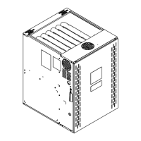
Instructions for removing furnace access panels for installation.

Horizontal Installation in an Attic or Crawlspace

Guidelines for installing the furnace in horizontal positions.

Gas Piping

Details on connecting the gas supply to the furnace.

Combustion and Input Check

Procedures for verifying combustion and input rate settings.

Gas Valve Adjustment

Steps for adjusting the furnace gas valve for proper operation.

High Altitude Derate

Procedures for adjusting furnace operation at high altitudes.

General Venting

Recommendations for furnace venting systems.

Air for Combustion and Ventilation

Requirements for providing adequate air for furnace operation.

Duct Connections

Guidance on connecting supply and return air ducts.

Horizontal Right and Downflow Furnace no Coil

Specific installation instructions for horizontal furnaces without coils.

Return Duct Connections

Instructions for installing return ductwork for the furnace.

Return Air Filters

Information on selecting and installing air filters for the furnace.

RETURN AIR FILTERS FOR FURNACE IN HORIZONTAL CONFIGURATION

Specific filter installation for horizontal furnace configurations.

Electrical Connections

Procedures for making electrical connections to the furnace.

Field Wiring

Diagrams and instructions for field wiring the furnace.

Twinning

Instructions for connecting two furnaces together.

General Start-up and Adjustment

Preliminary Inspections

Checks to perform before starting up the furnace.

Lighting Instructions

Procedures for lighting the furnace burners.

Control and Safety Switch Adjustment

Adjusting control and safety switches for proper function.

Furnace Combustion Air Exhaust Options

Combustion Air Conversions

Steps for converting combustion air exhaust options.

Integrated Furnace Control Menu

Integrated Furnace Control Display Codes

Fault Code Recovery

Procedures for clearing and viewing fault codes.

Belly Band Location

Setting Airflow

Troubleshooting

Troubleshooting Flowchart Index

An index of troubleshooting flowcharts for furnace issues.

GETTING STARTED

Initial steps for diagnosing furnace problems.

2.1 Fault Code

Troubleshooting steps for a specific fault code related to gas pressure.

2.2 Fault Code

Troubleshooting steps for a fault code related to gas valve operation.

2.3 Fault Code

Troubleshooting steps for a fault code related to gas valve energization.

3.1 Fault Code

Troubleshooting steps for a fault code indicating a pressure switch issue.

3.2 Fault Code

Troubleshooting steps for a fault code related to pressure switch operation.

4.0 Fault Code

Troubleshooting steps for a fault code related to limit switches.

4.0 Fault Code Flame Rollout

Troubleshooting steps for flame rollout faults.

05 Fault Code

Troubleshooting steps for a fault code indicating flame sensed when not required.

6.1 Fault Code

Troubleshooting steps for a polarity fault code.

6.2 Fault Code

Troubleshooting steps for a ground fault code.

6.3 Fault Code

Troubleshooting steps for igniter related fault codes.

7.1 Fault Code

Troubleshooting steps for an external gas valve circuit error.

08 Fault Code

Troubleshooting steps for low flame sense current.

11 Fault Code

Troubleshooting steps for IFC internal gas valve relay failures.

12 Fault Code

Troubleshooting steps for an open or missing onboard fuse.

Constant Torque Motor Troubleshooting

Sequence of Operation

Periodic Servicing Requirements

Related product manuals