A801X-SVX001-1A-EN
37
Electrical Connections
Make wiring connections to the unit as indicated on enclosed wiring diagram. As with all gas appliances using electrical power, this furnace shall
be connected into a permanently live electric circuit. It is recommended that furnace be provided with a separate "circuit protection device"
electric circuit. The furnace must be electrically grounded in accordance with local codes or in the absence of local codes with the National
Electrical Code, ANSI/NFPA 70 , if an external electrical source is utilized. The integrated furnace control is polarity sensitive. The hot leg
of the 120V power supply must be connected to the black power lead as indicated on the wiring diagram.
Refer to the Wiring Diagram section in this document and unit wiring diagram attached to furnace.
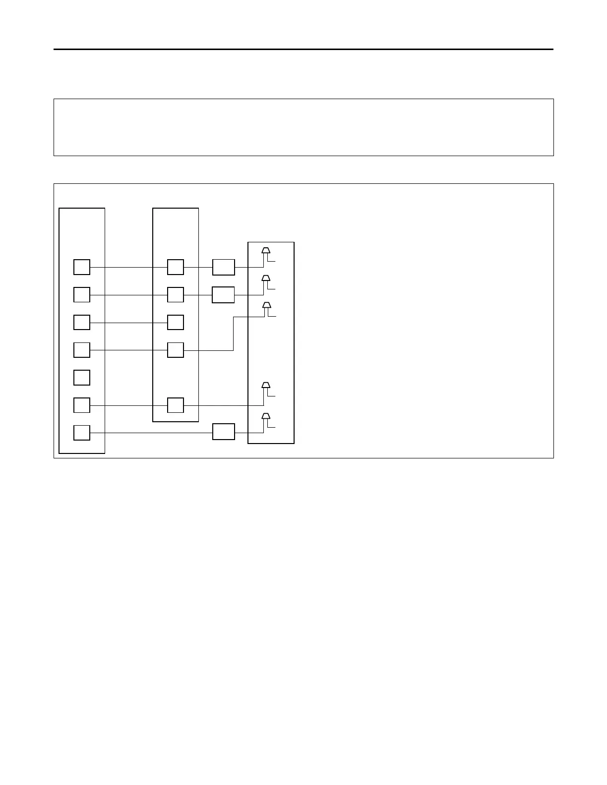
Field Wiring
O
Y1 Y1
B B
W1W1
GG
RR
Y1
Two Stage
Thermostat
Furnace
Outdoor Unit
(No Transformer)
O
R
X2
Y2
NOTES:
1) HP = Wiring used for Heat Pump systems.
2) Y1 must connect from the thermostat to the IFC
for proper airflow.
3) A/TCONT824 thermostats do not require the use of X2.
4) Y2 not available for A801X.
HP
HP
HP
FIELD WIRING DIAGRAM FOR A801X SINGLE STAGE
HEATING THERMOSTAT, ONE STAGE AC OR HEAT PUMP
B
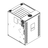
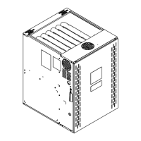
FFuurrnnaaccee GGeenneerraall IInnssttaallllaattiioonn
 Loading...