64
A952V-SVX001-1A-EN
Return Air Filters
TTYYPPIICCAALL UUPPFFLLOOWW RREETTUURRNN AAIIRR FFIILLTTEERR
IINNSSTTAALLLLAATTIIOONNSS
Filters are not factory supplied for upflow furnaces.
Filter size needed will be dependent on type of filter
and CFM requirement. Filters must be installed
externally to the unit.
IImmppoorrttaanntt:: It is recommended to transition return
ducting to the same size as the opening. It
is acceptable for return duct or filter frame
to extend forward of the opening but
plastic plugs MUST be installed in any
opening that the duct or filter frame may
cover.
Table 25. Upflow Return Air Filters
Furnace Width Filter
Qty and Size
17 – 1/2” 1 – 16” x 25” x 1”
21” 1 – 20” x 25” x 1”
24 – 1/2” 1 – 24” x 25” x 1”
Note: For upflow furnace models in any configuration, where the
airflow requirement exceeds 1600 CFM - Furnaces will
require return air openings and filters on: (1) both sides,
or (2) one side and the bottom, or (3) just on the bottom.
PPrreeppaarraattiioonn ffoorr UUppffllooww BBoottttoomm aanndd SSiiddee RReettuurrnn AAiirr
FFiilltteerr IInnssttaallllaattiioonnss
All return air duct systems should provide for
installation of return air filters.
1. Determine the appropriate position to set the
furnace in order to connect to existing supply and
return ductwork.
2. For upflow side return installations, remove the
insulation around the opening in the blower
compartment
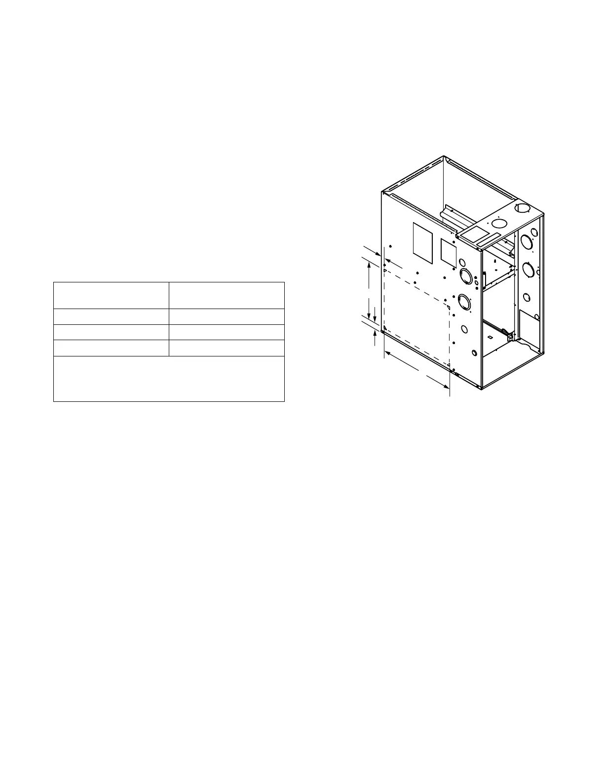
3. The side panels of the upflow furnace include
locating notches that are used as guides for cutting
an opening for return air, refer to the figure and the
upflow furnace outline drawing for duct connection
dimensions for various furnaces.
4. If a 3/4" flange is to be used for attaching the air
inlet duct, add to cut where indicated by dotted
lines. Cut corners diagonally and bend outward to
form flange.
5. If flanges are not required, and a filter frame is
installed, cut between locating notches as in
illustration.
6. The bottom panel of the upflow furnace must be
removed for bottom return air.
*
*
*
*
UPFLOW FURNACES ONLY
LOCATING
NOTCHES
PROVIDED
FOR SIDE
RETURN
CUTOUT
* SEE OUTLINE DRAWING
FRONT
OF FURNACE
1. UUppffllooww FFuurrnnaacceess::
When the upflow furnace is installed in the
horizontal right or left application and a return duct
is attached to the top side, do not install a filter in
the return duct directly above the furnace. Install
the filter in a remote location.
When the upflow furnace is installed in the
horizontal right or left application and a close
coupled (less than 36") return duct is attached to the
bottom side of the furnace as shown above,
securely attach a 1/2" mesh metal hardware cloth
protective screen to the inside bottom of the filter
grill ttoo pprreevveenntt ppeerrssoonnaall iinnjjuurryy ffrroomm ccoonnttaaccttiinngg
mmoovviinngg ppaarrttss wwhheenn rreeaacchhiinngg iinnttoo tthhee rreettuurrnn
ooppeenniinngg ttoo rreeppllaaccee tthhee ffiilltteerr..
Close coupled (less than 36") return (filter directly
beneath bottom side return) is not recommended
due to noise considerations.
2. Connect the duct work to the furnace. See Outline
Drawing for supply and return duct size and
location.
Flexible duct connectors are recommended to
connect both supply and return air ducts to the
furnace.