10
A952V-SVX001-1A-EN
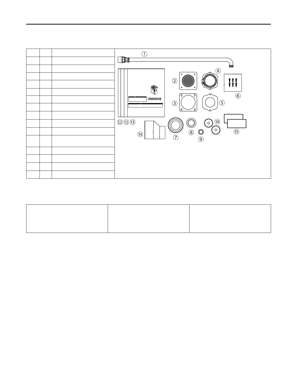
Document Pack Contents
Item
Qty. Description
SSAAFFEETTYY WWAARRNNIINNGG
Only qualified personnel should install and service the equipment. The installation, starting up, and servicing ofheating, ventilating, and air-conditioning
equipment canbe hazardous and requires specific knowledge and training. Improperly installed, adjusted or altered equipment by an unqualified person
could result in death or serious injury. When working on the equipment, observe all precautions in the literature andon the tags, stickers, and labels that
are attached to the equipment.
July 2022
AA995522VV--SSVVXX000011--11AA--EENN
Upow/Horizontal and Downow
Gas-Fired, Direct/Non-Direct Vent, 2–Stage
Condensing Variable Speed Furnaces
UUpp ff ll ooww ,, CCoo nnvveerrttiibbllee ttoo
HHoorrii zzoonnttaall RRiigg hhttoorr
HHoorrii zzoonnttaall LLeefftt
A952V040BU3SAC/D
A952V060BU4SAC/D
A952V080BU4SAC/D
A952V080CU5SAC/D
A952V100CU5SAC/D
A952V120DU5SAC/D
DDooww nnfflloo ww OOnnllyy
A952V040BD3SAC/D
A952V060BD3SAC/D
A952V080BD4SAC/D
A952V100CD5SAC/D
A952V120DD5SAC/D
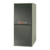
NNoo ttee::Graphics inthis document are for
representation only. Actual model may differ in
appearance.
CAUTION
!
Failure to follow this Caution could result in property damage or personal injury. 4GXC* and
4MXC* coils installed on upflow furnaces in vertical, horizontal left, or horizontal right
orientations without a factory installed metal drain pan shield must use a MAY*FERCOLKITAA
kit. Coils installed on upflow furnaces must have drain pans that are suitable for 400° F
(205°C) or have a metal drain pan shield. Downflow furnaces do not require a metal drain pan
shield or the use of the MAY*FERCOLKITAA kit.
COIL REQUIREMENT!
Installation, Operation, and Maintenance
1 1
Condensate Drain Tube Assembly
2 1
Inlet Vent
(a)
3 1 Inlet Vent Gasket
4 1
Outlet Vent Assembly
5 1 Outlet Vent Gasket
6 6 Screws
7 1
Condensate Trap Grommet
8 1
Plug - Condensate/Gas
9 1
Plug - Electrical
10 2
Grommet - Condensate/Gas
11 1
Installation, Operation, and
Maintenance
12 1 Owner Guide
13 1
Limited Warranty
14 1
2” to 3” Coupling - CPL00938
(b)
15 2
Brand labels
(c)
(a)
3” inlet vent supplied with A952V120DU5S and A952V120DD5S only. 2” inlet vent supplied with all other models.
(b)
Supplied with A952V120DU5S and A952V120DD5S only.
(c)
Place appropriate brand label below the warning label on the front panel using stencil marks as guides.
Part List
• Igniter
• Flame Sensor
• In-shot Burner(s)
• Gas Valve
• Inducer Assembly
• Blower Motor
• Blower Wheel
• IFC (Integrated Furnace Control)
• Pressure Switch(es)
• Main Thermal Limit
• Roll-Out Switch(es)
• Reverse Air Switch(es)
AAcccceessssoorriieess
A952V-SVX001-1A-EN