GF - F 2
Measuring Flame Current
Introduction
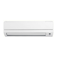
All communicating gas furnaces use the principle of
Flame Rectification to prove the presence of burner
flame. The flame rod circuit consists of a flame rod
assembly that is mounted at the opposite end of the
burner rack from the ignitor (Figure 1.)
Figure 1
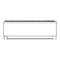
The flame rod assembly is connected to the furnace
control board via a wire (Figure 2.)
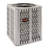
The wire connects to the 2-pin white plug on the fur-
nace control board (Figure 3.)
Flame rod
assembly
Figure 2
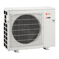
Electrical circuit
The flame rod will have AC voltage present when-
ever there is power to the furnace and the door switch
is pushed in. The voltage potential level on the flame
rod is below line voltage level. When the burners
light, a conductor path is made through the burner
flame (Figure 4.)
Figure 3
Figure 4

 Loading...