8 ACC-SVN67D-EN
Installation
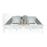
6. The electric heater element assembly has "BOTTOM" stamped in the mounting panel to identify
the proper position for mounting.
7. Refer to Tabl e 2 . If the unit/heater combination being installed is the same as any in this table
and the application is for horizontal airflow, the limit control TCO-A must be replaced with
the extra limit control shipped with the heater. Replace TCO-A following the instructions in
steps 8 and 9. If the unit/heater combination being installed does not correspond to any in this
table or if the application is for downflow airflow, skip steps 8 and 9 and go on to step 10.
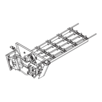
8. TCO-A is the limit control located in the center or right part of the heater mounting plate that
is located on the bottom of the two heater element assemblies. See Figure 4. To replace this
device, first remove the two wires connected to the terminals. Next, remove the two screws
which secure it to the heater element mounting plate. Once TCO-A has been removed from the
heater element mounting plate, discard this device.
Figure 3. Electric heater element panel
Table 2. TCO-A replaced for Horizontal Duct Configuration
Unit Model Number
Electric Heater Model
Number
TCO-A
location
TSC120E4**B BAYHTRA427, 436, 454 Right
TSC120EW**B BAYHTRAW36, W54 Right
WSC120EW BAYHTRBW36, W54 Right
THC072E4, WSC090E4 BAYHTRU427, 436 Center
WSC090EW BAYHTRUW27, W36 Center
WSC072E3 BAYHTRW327, 336 Center
TSC090E4, WSC072E4 BAYHTRW427, 436 Center
TSC090EW, WSC072EW BAYHTRWW27, W36 Center

 Loading...