ACC-SVN67D-EN 9
Installation
9. Obtain the replacement TCO-A which is secured with a wire tie near the unit/heater terminal
block located on the electric heater control panel. Attach it to the heater element mounting plate
with the two screws that were removed in step 8. Connect the two wires that were un-hooked
in step 8 to the terminals on the new TCO-A. Refer to the heater package wiring diagram to
assure that the wiring is connected properly.
Note: The back of the electric heater element assembly is supported by a factory installed Electric
Heat Support Rod Hanger or other sheet metal device in the unit.
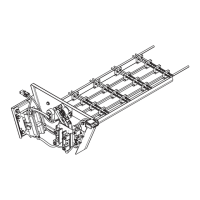
10. Tilt the back of the electric heater element assembly slightly upward as it is positioned in the
opening to engage the support rod with the support rod hanger. The BAYHTRA, BAYHTRB, and
BAYHTRD models will have a guide rod and a support bracket to help with the installation. See
Figure 5. Be very careful to avoid dragging the heater element on the edges of the opening in
vestibule panel, as this could damage or pinch the heater elements resulting in a short circuit.
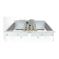
Engage the bottom edge of heater element panel with the two locator tabs. See Figure 3.
BAYHTRB and BAYHTRD kits will have 4 locator tabs along the top, a filler panel to be placed
below the heater, and 12 screws to attach the assembly in place. See Figure 6.
Figure 4.
TCO-A LOCATED ON THE RIGHT
TCO-A LOCATED IN THE CENTER

 Loading...