18-HE46D1-3B-EN 7
Installer’s Guide
LEDS
The control board contains two LEDs; one green and
one red surface mount. The green LED is a status indi-
catorlabeledLitePortonthecontrolboardandashes
at a 1/2 second on (plus fast blink at the end for LitePort
data)and1/2secondorateinthecoolingmode.In
the heating mode the green LED is full on with a blink/
ickerOFF(LitePortdatatransmission)everysecond.
The red LED is a small surface mount component lo-
cated near the end of the large capacitor. The red LED
is labeled ALERT on the control board. The red LED
indicatorisnormallyo.IftheredLEDisonorashing
then a fault is indicated according to the following:
RedLEDFlashing1/10SecondON–1/10SecondO–
Liquid Sensor Fault
RedLEDFlashing1/2SecondON–1/2SecondO–
Ambient Sensor Fault
Red LED continuously ON – I
2
C EEPROM Fault board
failurewhichcannotbeeldrepaired
If the cause of a fault is cleared or repaired then the red
LED fault indication will clear with the removal and reap-
plication of 24 VAC power (Y) to the control.
The solid state relay on the control module also contains
a green LED indicator. This LED indicates when the sol-
id state relay is energized by the control. If the control is
cyclingthefanthenthisLEDwillbeon/oaccordingly.
SYSTEM CHECK-OUT – COOLING UNITS ONLY
Verify that the control module is installed and wired per
the instructions contained within this installer’s guide.
(J5-Blue connected to “B”, J5-Yellow connected to “Y”,
J5-Orange connected to “Y”, Liquid sensor installed and
connected, ambient sensor installed and connected).
If uncertain about S2 dip switch 1, 2, 3, 4 settings, leave
in the factory preset position.
Apply power to the unit. Apply “Y” control signal.
VerifythegreenLEDisashingat1/2secondON1/2
second OFF rate.
Verify no red LED faults are present.
The fan should run continuously for a minimum of
10 seconds after “Y” is applied. After 10 seconds the
control may begin to cycle the fan if the ambient outdoor
temperature is 70 deg. or below. If the fan is cycling
and the outdoor temperature is below 70 deg., the
control is working. If after 10 seconds of “Y” application
the fan is on continuously, the TEST Switch (S1) may be
used to verify the Control Module has control over the
fan. Momentarily depress the TEST Switch (S1) on the
control board. The fan should then cycle 3 seconds on
then3secondsofor12seconds.
NOTE:
If the green LED on the control board is full on with
a blink/icker OFF every second make certain the
orange wire from the control board is connected to
“Y” per these instructions.
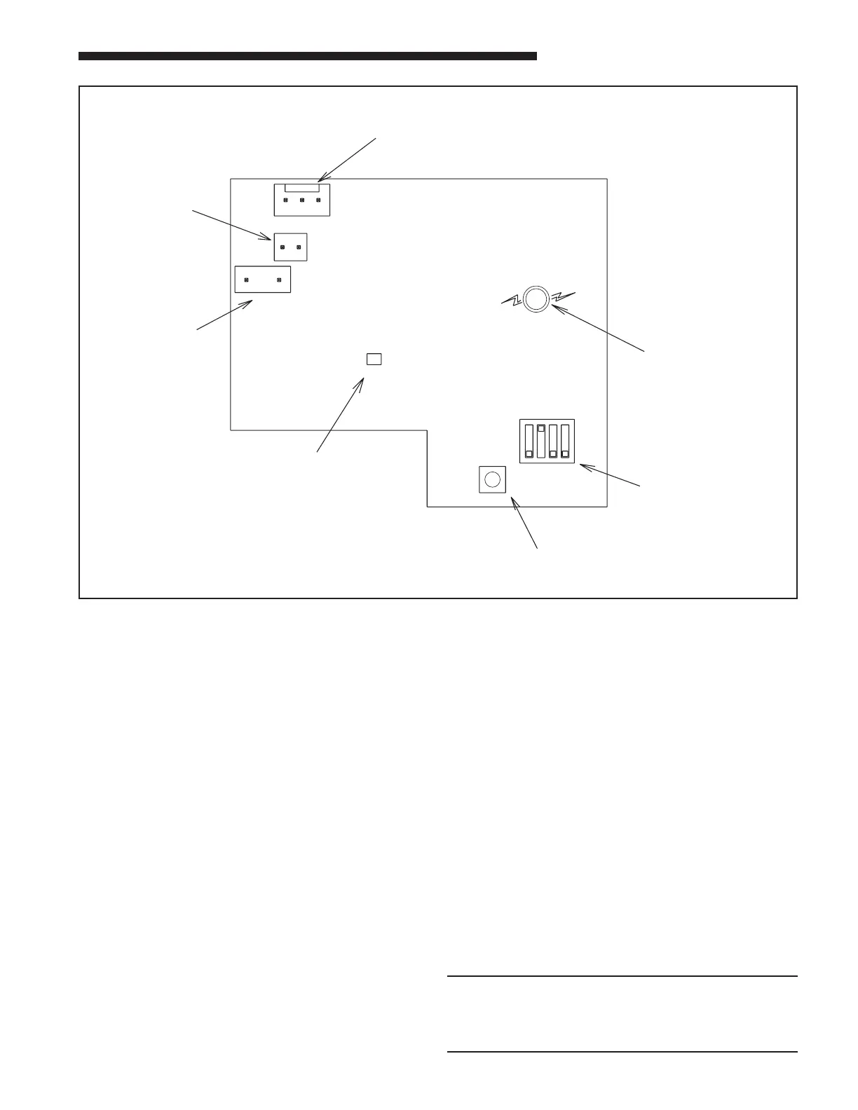
⑧
CONTROL BOARD
12 34
ON
OFF
S2
TEST
S1
J3
AMBIENT
J2
LIQUID
BYO
J5
ALERT
Lite
Port
RED
LED
GREEN
LED
S2-1,2,3,4
DIP SWITCHES
S1
TEST
SWITCH
AMBIENT
SENSOR
LIQUID
SENSOR
B,Y, O