26
CVHE-SVN04M-EN
recommended that larger size economizers be lifted
using overhead rigging.
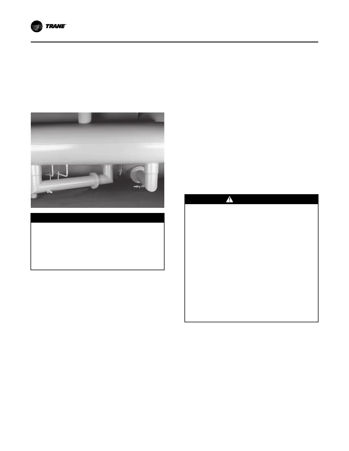
2. If the unit has insulation, remove the insulation and
loosen the bolts on the condenser liquid line flange.
See Figure 17. Do not remove the bolts at this time.
Cut the motor cooling drain line(s) if present and
cut entering and leaving 5/8 inch OD copper oil
cooler lines. Refer to Figure 17, p. 26.
Figure 17. Condenser liquid line flange
NNOOTTIICCEE
AAnnggllee VVaallvveess DDaammaaggee!!
RRiiggggiinngg,, hhaannddlliinngg,, aanndd ppllaacciinngg cchhiilllleerr ccoommppoonneennttss
oonn uunneevveenn ssuurrffaacceess ccaann ccaauussee ddaammaaggee ttoo aannggllee
vvaallvveess..
RReemmoovvee aannggllee vvaallvveess ttoo aavvooiidd bbrreeaakkaaggee dduurriinngg
hhaannddlliinngg iiff iitt iiss nneecceessssaarryy ttoo rreemmoovvee tthhee
eeccoonnoommiizzeerr..
NNoottee:: Take care to avoid damage to angle valves
during handling and transfer of economizer.
3. Loosen the bolts on the evaporator liquid line
flange. This connection is near the bottom of the
evaporator. See Figure 17, p. 26. Do not remove the
bolts at this time.
4. Economizers are connected to the condenser shell
via a bolted flange. See Figure 22, p. 29. Remove
the bolts at this flanged connection.
5. Loosen the economizer vent pipe bolts that secure
the vent pipes to the compressor interstage
castings (unless the compressor has already been
removed to gain vertical clearance.)
6. Secure economizer with appropriate rigging.
7. Remove the bolts from the condenser and
evaporator liquid line connection flanges. Adjust
the floor jack as necessary to support the weight of
the economizer.
8. Remove the economizer vent pipe flange bolts to
loosen the economizer. When the bolts are free,
back the economizer away from the chiller. The
economizer may tend to rotate off the jack towards
the chiller. Be prepared to offset the rotation.
9. Remove the economizer orifice plates and mark
them so they are reinstalled in their original
position. The orifice with the greatest number of
holes is to be located between the economizer and
the evaporator. The orifice with fewer holes is to be
located between the condenser and economizer.
10. Move the economizer away from the chiller and set
it on a pallet. Cover all openings to prevent the
entry of foreign material into the economizer,
condenser and compressor.
11. Use the reverse order to reassemble the
economizer on the chiller. Be sure to install new
gaskets at the appropriate joints.
12. Torque all bolts to specifications. Consult with your
Trane service group for specific torques for your
economizer design.
Tracer AdaptiView Display Arm
Removal
WWAARRNNIINNGG
HHaazzaarrddoouuss VVoollttaaggee ww//CCaappaacciittoorrss!!
FFaaiilluurree ttoo ddiissccoonnnneecctt ppoowweerr aanndd ddiisscchhaarrggee
ccaappaacciittoorrss bbeeffoorree sseerrvviicciinngg ccoouulldd rreessuulltt iinn ddeeaatthh oorr
sseerriioouuss iinnjjuurryy..
DDiissccoonnnneecctt aallll eelleeccttrriicc ppoowweerr,, iinncclluuddiinngg rreemmoottee
ddiissccoonnnneeccttss aanndd ddiisscchhaarrggee aallll mmoottoorr ssttaarrtt//rruunn
ccaappaacciittoorrss bbeeffoorree sseerrvviicciinngg.. FFoollllooww pprrooppeerr
lloocckkoouutt//ttaaggoouutt pprroocceedduurreess ttoo eennssuurree tthhee ppoowweerr
ccaannnnoott bbee iinnaaddvveerrtteennttllyy eenneerrggiizzeedd.. FFoorr vvaarriiaabbllee
ffrreeqquueennccyy ddrriivveess oorr ootthheerr eenneerrggyy ssttoorriinngg
ccoommppoonneennttss pprroovviiddeedd bbyy TTrraannee oorr ootthheerrss,, rreeffeerr ttoo
tthhee aapppprroopprriiaattee mmaannuuffaaccttuurreerr’’ss lliitteerraattuurree ffoorr
aalllloowwaabbllee wwaaiittiinngg ppeerriiooddss ffoorr ddiisscchhaarrggee ooff
ccaappaacciittoorrss.. VVeerriiffyy wwiitthh aa CCAATT IIIIII oorr IIVV vvoollttmmeetteerr
rraatteedd ppeerr NNFFPPAA 7700EE tthhaatt aallll ccaappaacciittoorrss hhaavvee
ddiisscchhaarrggeedd..
FFoorr aaddddiittiioonnaall iinnffoorrmmaattiioonn rreeggaarrddiinngg tthhee ssaaffee
ddiisscchhaarrggee ooff ccaappaacciittoorrss,, sseeee PPRROODD--SSVVBB0066**--EENN..
Use the following steps to remove the Tracer
AdaptiView™ display arm if additional clearance is
required.
1. Cut tie wraps holding wires inside of control arm
and remove wires from arm.
2. Remove 3-3/8-in. bolts from the angle bracket
attached to the control panel mounting bracket.
3. Use the reverse order to re-attach the arm to the
control panel mounting bracket.
DDiissaasssseemmbbllyy