Drive and Cabinet
AFDK-SVU01C-EN 17
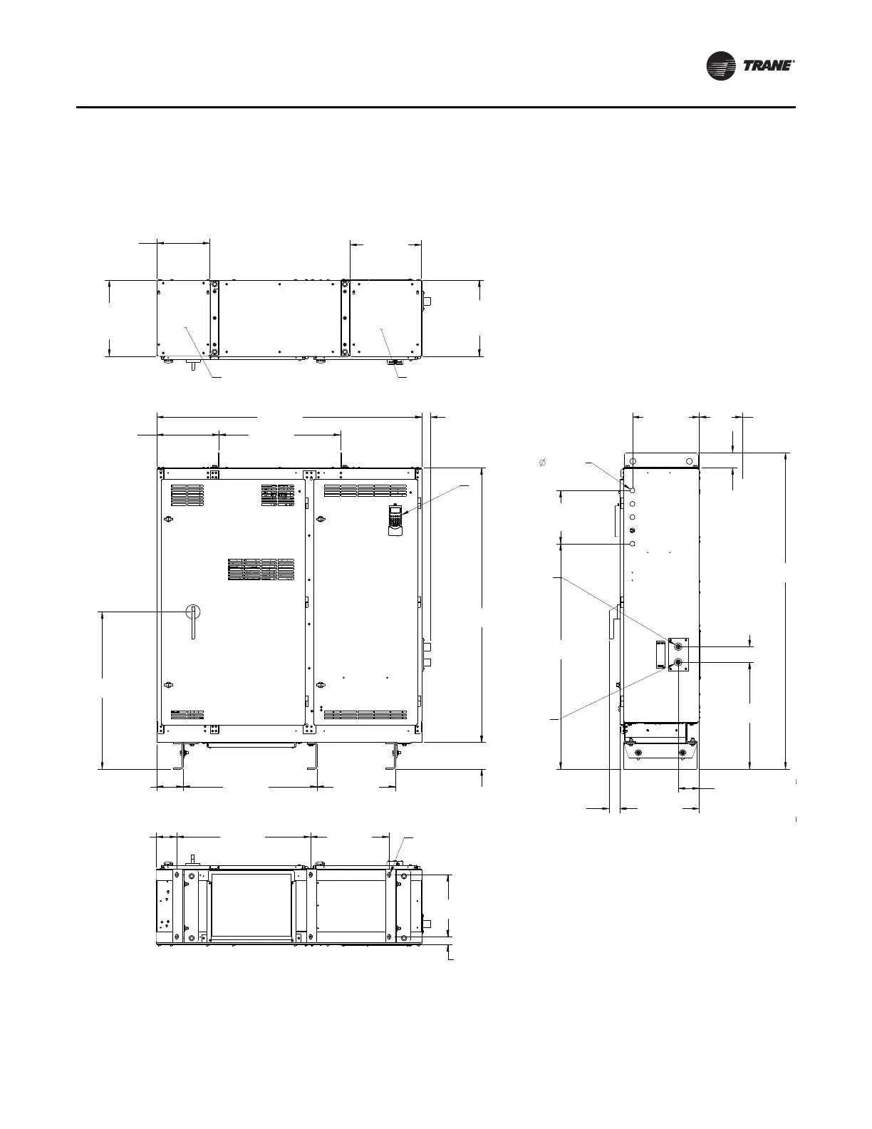
About the Cabinet
This section provides cabinet dimension information and
shows where the wire entry areas and liquid-cooling
connection points are located.
Figure 7, p. 17 and Figure 8, p. 18 show overall
di
mension
s for Frame 3 units; Figure 9, p. 19 and
Figure 10, p. 20 show overall dimensions for Frame 4
units.
Figure 7.
Drive cabinet dimensions: Frame 3 (dimensions shown in inches)
(a)
(a)Material courtesy of Rockwell.
2.380 18.000
30.250 17.7504.625
6.000 30.250 17.750
6.000
[6.0000]
62.000
14.124 27.445
60.000
71.500
3.500
50.896
3.500
24.125
4.750
PANEL
INPUT WIRING
17.208
11.875
17.208
OUTPUT WIRING
PANEL
16.181
35.500
1.911 15.104
4 SPACES@ 3.000
12.000
1.125
LCD OIM
COOLANT OUTPUT
3/4 NPT
COOLANT INPUT
3/4 NPT
DRIVE TUBE C
(CUSTOME
(6) 1/2 1
INPUT WIRING
PANEL
10.6 X 15.3 OPENING WITH
COVER REMOVED
OUTPUT WIRING
PANEL
13.8 X 13.8 OPENING WITH
COVER REMOVED
.625 X 1.25 FULL RAD SLOT
6 PLACES
6.00
MINIMUM
WALL
CLEARANCE
Top View
Front View
Side View
14.000
30.250 17.7504.625
1.813
.625 X 1.25 FULL RAD SLOT
6 PLACES
Bottom View