18-GJ92D1-1A-EN 3
INSTALLER'S GUIDE
7. Button Press AHC Configuration Method: Method #2
Replacement AHC will need to be configured for unit size. Airflow will be set at 400 cfm/ton based on unit size configura-
tion. These configurations can be done through the Diagnostics Mobile App with no manual steps or can be done manu-
ally without the Diagnostics Mobile App.
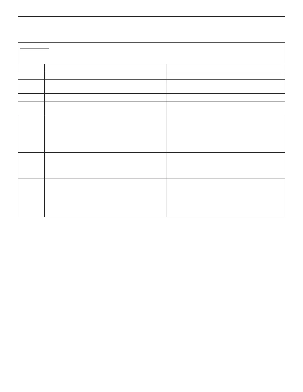
Step Manual Program Unit Model Size Red LED Status
1 Hold J13 BLE button down for 5 seconds and release Red LED will be off
2 Now entering programming
1 Red LED flash alerts user that it is now able to
program
3 If a configuration is present, will announce now Red LED will be off if no configuration is present
4
If no configuration is present, AHC will inform you it is
ready to program
5 quick Red LED flashes
5
After 5 quick flashes, start programming within 2 sec-
onds by pressing J13 button. Red LED will also flash
with each button press
1 press= TAMXB0A24
2 press= TAMXB0B30
3 press= TAMXB0C36
4 press= TAMXB0C42
5 press= TAMXB0C48
6 press= TAMXB0C60
6
2 seconds after the last button press, the Red LED
will flash 1 time to acknowledge programming
Red LED will now flash the number of times you
pressed to confirm your configuration. If you pro-
grammed the wrong size, within 2 seconds, start
step 5 over
7
If the configuration is correct and the BLE button has
not been pressed for 2 seconds, Red LED will an-
nounce successful programming.
After conguration, power cycle the air
handler.
Red LED will turn on for 5 seconds announcing the
configuration has been stored in NV memory cor-
rectly. Red LED will be on for only 2 seconds if not
stored properly. Programming is complete.
8. Replacement AHC Configuration – LINK Communicating Mode:
The System Controller (SC360) will load important parameters in communicating mode and no interaction is necessary
when replacing the AHC. IF the AHC and the System Controller (SC360) need replaced at the same time - contact your
local FSR or technical support agent.
Table 1: Conguration for Replacement AHC