CVGF-SVN02B-E4
60
Installation:
Electrical
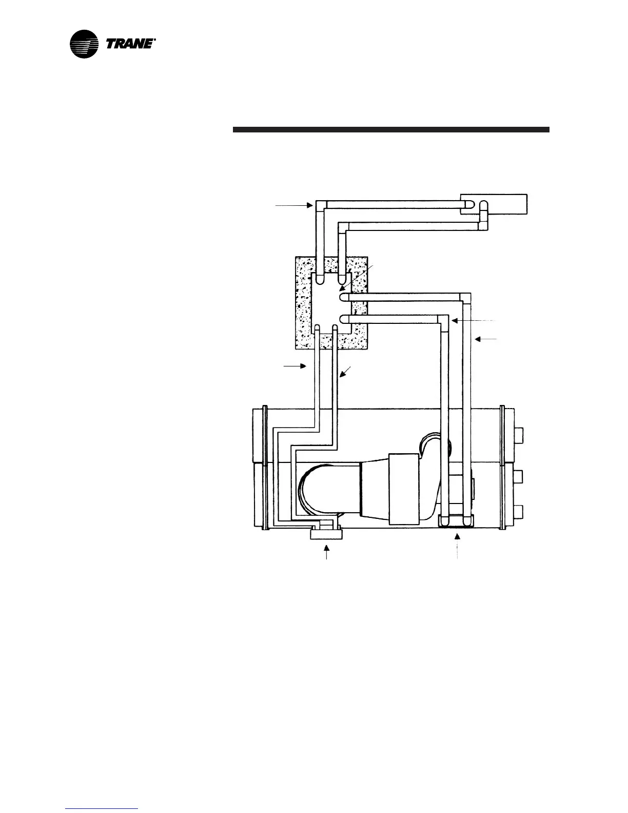
Figure 17. Typical equipment room layout with remote-mounted
Wye-Delta starter
Line side
power
wiring
Remote-mounted starter
Load power
wiring
115 Volt control
conduit
See Note 2
IPC circuit
conduit <30V
See Note 3
Motor terminal box
Notes:
1. Refer to the unit field connection diagram for approximate UCP
knockout locations.
2. 115-volt conduit must enter the higher than 30 Vdc Class I portion
of the unit control panel.
3. IPC circuit conduit must enter the Low Voltage Class II portion of
the UCP.
4. See starter submittal drawing for location of incoming wiring to
the starter.