CVHE-SB-32A 53
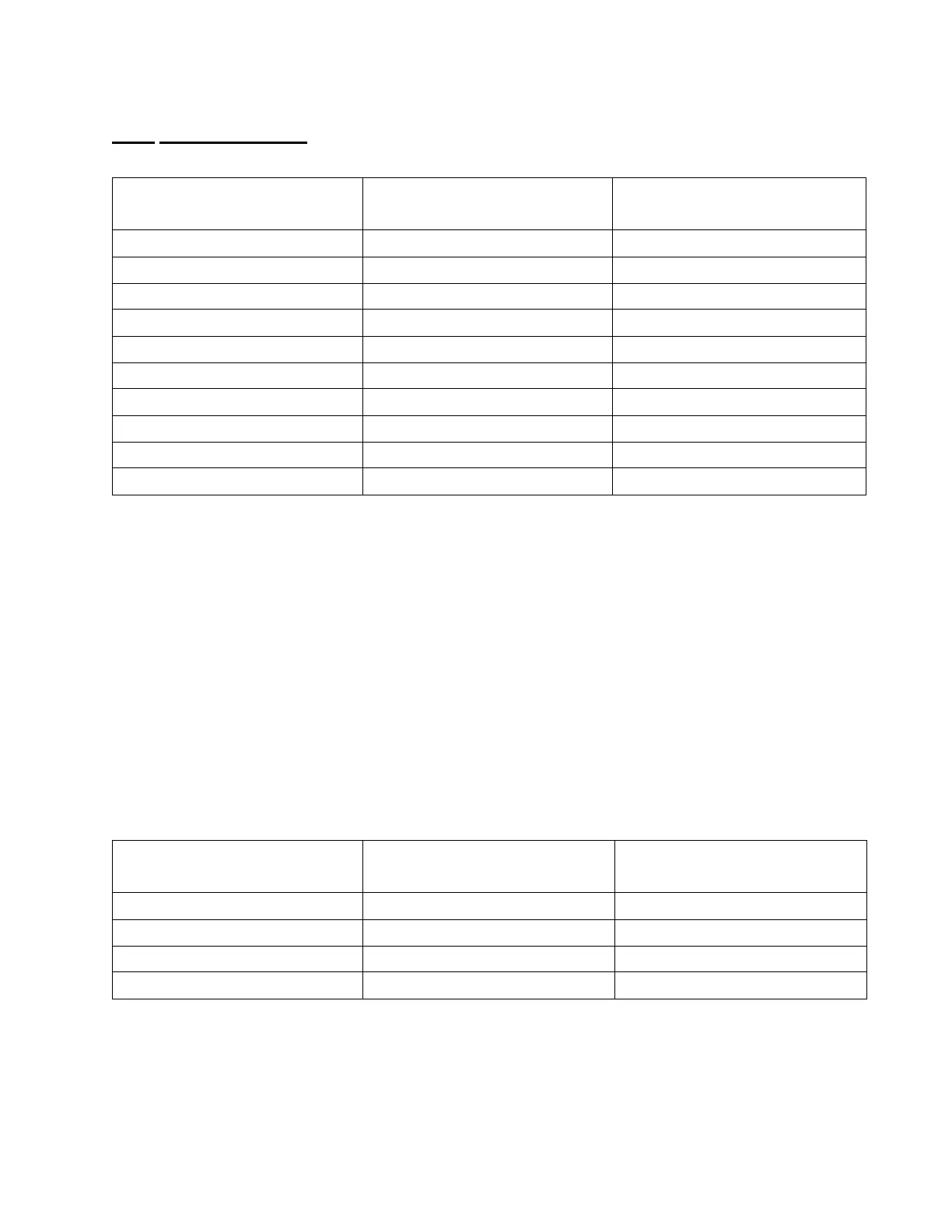
Table 7
Motor Winding Resistance
7 If the winding resistance is in the range, plug the J connector back into the appropriate
socket.
8 Perform steps 3-7 for each winding of the motor on the Stepper module.
9 If there is a short or an open, you will need to check the wiring to the motor, and then check
the motor.
10 If the windings resistance check passes, and you have not measured the Stepper module
voltages while it is powered, then plug J2 back into the module and go back to Section II,
Quick Test of Stepper Board.
B. If you need to disconnect the wires going to the motor for any reason, Table 8 is a wiring
table you can use to reconnect them.
Table 8
Stepper Motor Connections
J6 or J8 Connector Pin
Acceptable DC Resistance
Range CLV Nominal Resistance
(4 to 3) Open Circuit NA
(4 to 2): WI 50 mOhm to 5 Ohm 1.68 Ohm
(4 to 1) Open Circuit N/A
(3 to 2) Open Circuit N/A
(3 to 1):W2 50 mOhm to 5 Ohm 1.68 Ohm
(2 to 1) Open Circuit N/A
(4 to Conduit) Open Circuit N/A
(3 to Conduit) Open Circuit N/A
(2 to conduit) Open Circuit N/A
(1 to conduit) Open Circuit N/A
JB or J8 Connector Pin# on
Stepper
Motor Winding Output Signal
Name
Stepper Motor Terminal
Connection
4 1+ 3
3 2+ 5
2 1- 1
1 2- 4

 Loading...


