MUA-SVX01A-EN • Direct-Fired Make-up Air 69
Trouble Shooting
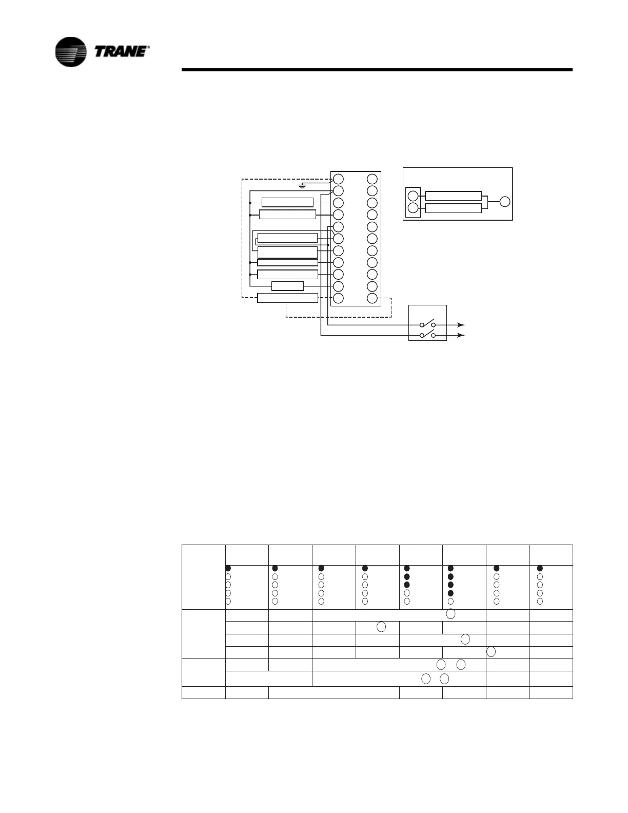
1. RM7895, RM7896; 120 VAC, 50/60 HZ; EC7895; 220-240 VAC, 50/60 HZ Power
Supply. Provide disconnect means and overload protection as required.
2. Do not connect any wires to unused terminals.
3. For EC7895, A 220 to 240 VAC to 120 VAC, 10 VA minimum stepdown
transformer (not provided) must be used to drive the shutter.
4. See flame detector specifications for correct wiring.
5. For RM7896A1048 (only), Ignition Terminal 1 is de-energized when flame is
proven.
6. Airflow switch check feature is for the RM7895, RM7896B.
7. RM7896A,B (only).
Figure 24. Wiring subbase and sequence chart for RM7895A/B, EC7895A,
RM7896A/B
G
L2
3
4
5
6
7
8
9
10
F
10
8
L2
12
13
14
15
16
17
18
19
20
21
22
Q7800
Line Voltage Alarm
Blower Motor (Blower)
Intermittent Pilot Ignition
Main Fuel Valve(s)
Ignition
Flame Detector
Master
Switch
L1 (Hot)
L2
(See Note 1)
Burner Controller/Limits
Lockout Interlock
Including Airflow Sw.
(See Note 4)
(See Note 3)
(See Note 2)
Ignition Transformer
Main Valve
For Direct Spark Ignition
(Oil or Gas)
L1
LED Display
Initiate Standby Start Time Purge
PFEP
4-10 Sec.
Run
Post Purge
7
15 Sec.
Standby
Power Power Power Power
Pilot
Flame
Main
Alarm
Power
Pilot
Flame
Main
Alarm
Power
Pilot
Flame
Main
Alarm
Power
Pilot
Flame
Main
Alarm
Power
Pilot
Flame
Main
Alarm
Burner Start
7 etoNrotoM rewolB/renruB
Ignition
5
Ignition/Pilot
Main Valve
Operating
Controls and
Interlocks
Limits and Burner Controller Closed to
Airflow Switch Check
6
CSFA ot desolC kcolretnI tuokcoL
CSSgnivorP emalFkcehC tratS efaSlangiS emalF
4
10
8
8
L1 6
6 7