Do you have a question about the Trane DFOA and is the answer not in the manual?
Provides guidance on the manual's scope, purpose, and importance for proper unit operation and maintenance.
Explains the meaning of warning symbols (WARNING, CAUTION) used to alert users to potential hazards.
Describes how unit model numbers identify specific unit types, components, and options for ordering and service.
Details safety precautions for electrical, mechanical, and other potential hazards during maintenance and troubleshooting.
Warns about risks associated with fuel substances and flammable vapors, emphasizing proper installation and setup.
Instructs to disconnect all electric power before servicing to prevent electrocution.
Outlines initial checks and requirements for unit installation and start-up, including electrical and gas connections.
Explains the alphanumeric coding system for DFIA units, detailing how each digit defines specific features and specifications.
Lists various gas train approval codes (No Selection, Standard, IRI, FM) relevant to unit configuration.
Provides a detailed list of MBH input ratings for natural gas and propane, corresponding to specific alphanumeric codes.
Details the horsepower ratings for blower motors, mapping them to specific alphanumeric codes for unit configuration.
Explains motor speed and starter options, including single-speed and two-speed configurations, with corresponding alphanumeric codes.
Describes various fan arrangements (horizontal, vertical) and their corresponding alphanumeric codes for unit configuration.
Lists options for V-bank filter sections (none, permanent, without, TA, pleated filters) and their alphanumeric designations.
Details various damper and mixing box configurations (no damper, motorized, mixing box types) and their alphanumeric codes.
Specifies the option for an Ultra Violet (UV) flame sensor, identified by the alphanumeric code 'AL'.
Details the option for a clogged filter indicator, denoted by the alphanumeric code 'AN'.
Explains the exhaust interlock option, represented by the alphanumeric code 'AP'.
Describes the interlocking relay option, identified by the alphanumeric code 'AQ'.
Explains the alphanumeric coding system for DFOA units, detailing how each digit defines specific features and specifications.
Lists various gas train approval codes (No Selection, Standard, IRI, FM) relevant to unit configuration.
Provides a detailed list of MBH input ratings for natural gas and propane, corresponding to specific alphanumeric codes.
Details the horsepower ratings for blower motors, mapping them to specific alphanumeric codes for unit configuration.
Explains motor speed and starter options, including single-speed and two-speed configurations, with corresponding alphanumeric codes.
Describes various fan arrangements (horizontal, vertical) and their corresponding alphanumeric codes for unit configuration.
Lists options for inlet hood and birdscreen configurations (none, with permanent filters, without permanent filters) and their alphanumeric designations.
Lists options for V-bank filter sections (none, permanent, without, TA, pleated filters) and their alphanumeric designations.
Details options for motorized outlet dampers (none, motorized) and their alphanumeric codes.
Specifies insulation options for the unit (insulation on entire unit), identified by the alphanumeric code 'D'.
Describes internal blower/motor isolation options, identified by the alphanumeric code 'F'.
Details the option for extended grease lines, represented by the alphanumeric code 'G'.
Specifies the option for a low gas pressure burner, identified by the alphanumeric code '8'.
Lists vibration options for the unit (vibration feet-full unit), identified by the alphanumeric code 'Z'.
Details control options (7-day timer, setback thermostat, BACview) and their alphanumeric codes.
Specifies discharge louver options (discharge louver), identified by the alphanumeric code 'M'.
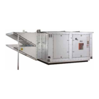
Illustrates and describes horizontal unit arrangements, detailing fan positions and discharge orientations.
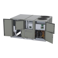
Illustrates and describes vertical DFOA unit arrangements, showing fan positions and side discharge configurations.
Illustrates and describes vertical DFIA unit arrangements, showing fan positions, discharge types, and electrical cabinet (EC) location.
Presents detailed specifications for DFIA and DFOA units, including airflow, heating data, fan sizes, motor HP, and filter dimensions.
Warns about fiberglass wool in the product and potential health risks from airborne particles during handling.
Provides guidance on inspecting the unit for damage during shipment and filing claims if necessary.
Outlines the installer's duty to inspect and correct any issues that may arise during shipment and installation.
Details checks for unit data plates, labels, and components to ensure correct specifications and proper assembly.
Presents a plan view diagram of DFIA units and a table detailing approximate weights of various components for DFIA models.
Specifies required clearances around the unit for operation, maintenance, and shaft replacement.
Presents a plan view diagram of DFOA units and a table detailing approximate weights of various components for DFOA models.
Specifies required clearances around the unit for operation, maintenance, and shaft replacement.
Provides recommendations for rigging and suspending units, including lifting points, sling spreader requirements, and vibration isolator placement.
Illustrates typical vibration feet assembly for indoor units, showing mounting details and dimensions.
Shows a plan view of unit sections with typical vibration mounts indicated.
Illustrates typical hanging assemblies for indoor units, distinguishing between unobstructed and obstructed holes.
Shows a plan view of unit sections with typical hanging points indicated.
Details requirements for verifying compliance with codes and consulting authorities before installation.
Specifies Canadian installation compliance with local building codes and CAN/CGA-B149.
Warns against installing the unit in corrosive or flammable atmospheres, or where combustion air contains harmful vapors.
Provides instructions for rigging, moving, and inspecting the unit, emphasizing the use of lifting lugs and checking electrical connections.
Guides on selecting a unit location, emphasizing level placement and checking clearances to combustible materials.
Warns about maintaining proper clearances between heat exchanger, vent surfaces and combustible materials to prevent fire hazards.
Instructs to set roof curbs and rooftop units level for proper operation and conform to codes.
Details requirements for roof support, including load capacity and referencing unit weights from tables.
Emphasizes placing the unit in a location accessible for service personnel to prevent injury or death.
Provides detailed steps for assembling and installing roof curbs, ensuring squaring, leveling, and sealing.
Lists sequential steps for installing the roof curb, including positioning rails and tightening bolts.
Explains the purpose and construction of hood supports, detailing material requirements and placement for unit accessories.
Illustrates roof curb details, including dimensions, materials, and assembly components.
Provides diagrams and tables for DFOA roof curb dimensions for models 109-118, including details for single blower configurations.
Provides diagrams and tables for DFOA roof curb dimensions for models 215-230, including details for double blower configurations.
Illustrates DFOA roof curb dimensions for models 109-118 with return air downstream of the burner.
Illustrates DFOA roof curb dimensions for models 215-230 with return air downstream of the burner.
Illustrates DFOA roof curb dimensions for models 109-118 when equipped with a mixing box.
Provides dimensions for DFOA roof curbs (models 215-230) when equipped with a mixing box.
Guides on placing accessories within the fan section and ensuring proper design for field-constructed intake accessories.
Details safety warnings for hazardous voltage and live electrical components, and outlines connection requirements per codes.
Provides requirements for gas piping installation according to codes, including ground unions, drip legs, and shut-off valves.
Warns against performing pressure/leak tests on gas piping while connected to the unit, to prevent gas valve damage.
Advises against using open flames to detect gas leaks due to explosion hazards.
Warns about the dangers of gas leaks and explosive conditions, emphasizing leak detection methods.
Guides on connecting power, remote controls, thermostats, and sensors according to wiring diagrams.
Provides advice on mounting thermostats to avoid direct heat impact and ensure proper readings, and discusses ventilation for recirculating units.
Warns about risks of excessive recirculation or insufficient ventilation air, potentially causing hazardous combustion product concentrations.
Emphasizes the presence of the owner's representative during start-up for instructions and notes factory testing of equipment.
Details safety precautions for electrical, mechanical, and other potential hazards during maintenance and troubleshooting.
Outlines a detailed pre-start inspection process to ensure unit condition, insulation security, and proper component installation.
Provides warnings about potential equipment damage, such as from rupturing grease seals or overtightening belts.
Instructs to read sequences and schematics before starting, check voltage, blower rotation, and damper operation.
Details safety precautions for electrical, mechanical, and other potential hazards during maintenance and troubleshooting.
Guides on checking gas pressure, pilot valve, and ensuring proper operation for systems with a pilot.
Explains how to monitor and adjust the flame signal using a voltmeter or VOM for optimal performance.
Provides steps for setting the main flame, including manometer use, gas valve adjustments, and burner light-off.
Details procedures for Extended Shutdown and Emergency Shutdown, including turning off switches and closing valves.
Presents a checklist form for documenting unit checks and start-up procedures, ensuring satisfactory operation.
Provides a table of motor full load amps (FLA) for various HP ratings and voltages, for single and three-phase motors.
Lists transformer ampacity ratings based on primary voltage (VA) for calculating electrical requirements.
Explains how to calculate the unit's FLA and MCA based on the presence of service receptacles and motor types.
Warns about fiberglass wool in the product and potential health risks from airborne particles during handling.
Provides guidance on inspecting the unit for damage during shipment and filing claims if necessary.
Outlines the installer's duty to inspect and correct any issues that may arise during shipment and installation.
Details checks for unit data plates, labels, and components to ensure correct specifications and proper assembly.
Warns about potential hazards when working with live electrical components during installation, testing, and servicing.
Describes the operating sequence for summer mode, including switch positions, interlocks, and damper operation.
Details the operating sequence for winter mode, covering pre-purge, ignition trials, and main flame modulation.
Outlines periodic maintenance tasks essential for efficient operation and extended service life, including checks after 8 hours and monthly tasks.
Details safety precautions for electrical, mechanical, and other potential hazards during maintenance and troubleshooting.
Warns about risks from fuel substances and flammable vapors, emphasizing proper installation and setup.
Provides warnings about potential equipment damage, such as from overtightening belts or improper handling.
Lists quarterly maintenance tasks, including belt checks, bearing inspections, pilot system checks, and safety control operation.
Details yearly maintenance procedures, covering fan wheels, bearings, electrical components, and vent inspections.
Explains lubrication needs for blower motors and pillow block bearings, identifying motors that require or do not require lubrication.
Warns against over-greasing bearings, which can cause overheating and damage.
Provides guidance on lubricating pillow block bearings, including prelubrication, re-lubrication, and signs of proper lubrication.
Details the frequency of lubrication based on operating conditions, bearing temperature, and speed, presented in a table.
Instructs on inspecting and lubricating damper linkages and bearings for smooth operation, especially for larger dampers.
Guides on checking and replacing air filters based on differential pressure, and advises on cleaning and recoating washable filters.
Explains how to adjust belt tension to prevent slippage without over-tensioning, and the impact of adjustments on unit air balance.
Warns that overtightening belts or altering pulley pitch can cause unit imbalance or motor failure.
Provides a step-by-step method for checking and adjusting V-belt tension, including deflection measurements and force comparisons.
Emphasizes keeping coil surfaces clean for rated efficiency and using non-corrosive cleaning solutions.
Warns about potential damage to coil fins when using high-pressure spray for cleaning.
Advises periodic flushing of the condensate pan and drain system with a water hose.
Instructs on inspecting and replacing gaskets used on doors, covers, filter racks, and dampers as needed.
Recommends yearly inspection of heating installations and provides a procedure for checking burner assembly, mixing plates, and ports.
Instructs to disconnect all electric power before servicing to prevent electrocution.
Warns about maintaining proper clearances to prevent fire hazards and potential injury or damage.
Advises against enlarging burner ports, as it can affect equipment performance, and checks for hairline cracks in mixing plates.
Warns about risks from fuel substances and flammable vapors, emphasizing proper installation and setup.
Details initial and annual inspection of gas ports for scale or debris, and methods for cleaning them.
Explains how the direct-fired gas burner operates, detailing airflow, gas supply, and flame zones at different firing rates.
Illustrates the direct-fired gas heater's burner section, showing airflow, gas supply, and flame zones.
Provides a detailed view of the gas burner section, showing components like the flame rod, spark ignitor, and gas manifold.
Provides instructions for adjusting MR212 and M411/511/611 valves for high and low fire manifold adjustments.
Illustrates valve adjustments for MR212 valves, showing control points for high and low fire settings.
Details steps for adjusting M411, 511, 611 valves for high fire manifold pressure settings.
Provides instructions for adjusting MR212 valves for low fire manifold adjustments.
Details safety precautions for electrical, mechanical, and other potential hazards during maintenance and troubleshooting.
Guides on troubleshooting MDT controls, including sensor replacement, voltage checks, and valve response.
Provides steps for connecting Modulating Room Temperature (MRT) controls and troubleshooting common issues.
Details wiring and testing procedures for Modulating Room Temperature (MRT) controls, including sections for initial setup and checks.
Continues troubleshooting steps for MDT/MRT controls, including wire diagrams and observing burner operation.
Outlines observing burner flames and pressure as a test potentiometer is turned through its range for MDT/MRT controls.
Details section 4 of MDT/MRT control troubleshooting, focusing on wiring, temperature selectors, and delivered air temperature checks.
Provides a table correlating temperature readings with resistance values for RTC (Remote Temperature Control) sensors.
Introduces troubleshooting for flame relays, emphasizing safety procedures and providing a guide for common problems and their causes.
Details safety precautions for electrical, mechanical, and other potential hazards during maintenance and troubleshooting.
Lists symptoms and probable causes for safety shutdown (lockout) during various flame relay operating periods.
Continues the troubleshooting guide for flame relays, detailing issues during the 'Run Period' and their potential causes.
Illustrates the wiring subbase and sequence chart for specific Honeywell flame relay models, including terminal assignments.
Illustrates the wiring subbase and sequence chart for Honeywell flame relay models RM7895C/D and RM7896C/D.
Explains the operation of Honeywell flame relays (RM7895, EC7895, RM7896), covering Initiate, Standby, and Normal Start-up Prepurge sequences.
Describes the normal operating sequence of Honeywell flame relays, including LED indications and sequence initiation.
Details the initiate sequence for Honeywell flame relays, including causes for hold conditions and the role of burner motor starters.
Explains the standby state for Honeywell flame relays, where the module awaits a call for heat from the operating control.
Describes the pilot flame establishing period (PFEP) and main flame establishing period (MFEP) for Honeywell flame relays.
Explains the 'run' period for specific Honeywell flame relay models and the function of the Run/Test Switch.
Illustrates the sequence status LEDs on Honeywell burner control units, indicating operational states.
Shows selectable configuration jumpers on Honeywell burner controls, used for setting various operational parameters.
Explains the three site-configurable jumper options on Honeywell relay modules for adjusting safety levels and actions.
Lists jumper options (JR1, JR2, JR3) for Honeywell flame relay modules, detailing their function and effect when intact or clipped.
Provides guidance on operating and troubleshooting the direct spark ignition control gas valve and two-stage valves.
Warns about maintaining proper clearances to prevent fire hazards and potential injury or damage.
Describes the operation of the direct spark ignition gas valve, including prepurge, ignition, and flame loss procedures.
Details procedures for checking and adjusting high and low pressure regulator settings for two-stage gas valves.
Continues troubleshooting for gas control valves, including checking gas pressure, manifold pressure, and safety shutdown performance.
Outlines steps to check safety shutdown performance by testing ignition, gas flow, and thermostat operation.
Illustrates the spark rod, including its dimensions and bending instructions for proper installation and function.
Details safety precautions for electrical, mechanical, and other potential hazards during maintenance and troubleshooting.
Provides a guide for troubleshooting systems with pilot ignition, covering blower operation, voltage, and damper issues.
Continues troubleshooting for pilot systems, addressing flame safeguard relay issues, pilot ignition, and gas pressure.
Continues troubleshooting for pilot systems, covering issues with pilot light, heat output, and burner response to temperature.
Continues troubleshooting for pilot systems, addressing damper operation, flame length, and burner speed issues.
Provides troubleshooting steps for MDT controls, covering gas flow, low fire, high fire, and sensor circuit issues.
Continues MDT control troubleshooting, addressing minimum fire, continuous high fire, and flame stability issues.
Continues MDT control troubleshooting, covering discharge air temperature errors and transformer issues.
Continues MDT control troubleshooting, addressing low discharge air temperature and setpoint issues.
Provides troubleshooting for MRT controls, starting with no gas flow and modulating valve installation issues.
Continues MRT control troubleshooting, covering continuous low fire (electronics problem/ok) and incorrect low fire issues.
Continues MRT control troubleshooting, addressing continuous high fire, incorrect high fire, and minimum discharge air temperature.
Continues MRT control troubleshooting, covering incorrect discharge air temperature and burned out transformer issues.
Continues MRT control troubleshooting, addressing incorrect space temperature and insufficient burner capacity.
Details Trane's standard parts-only warranty and optional extended warranty coverage periods and conditions.
Specifies the standard warranty as parts-only, lasting 12 months from startup or 18 months from shipment.
Describes the optional extended warranty, covering the second through fifth year after the standard warranty expires.
| Brand | Trane |
|---|---|
| Model | DFOA |
| Category | Air Conditioner |
| Language | English |