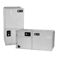
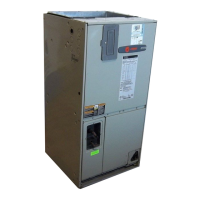
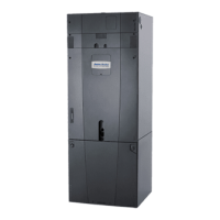
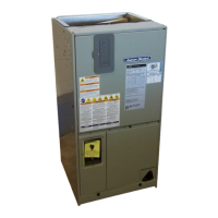
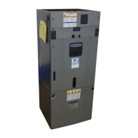
Figure 3. Typical W_HE casings 2 through 9 clearances for single or multiple unit installation
Notes:
2. A minimum clearance of 2’ 4-1/2” is required to open the hinged
control panel doors on Casing 9, 90-130 ton units.
3. Increase the clearance between staggered units by 150% of the
minimum clearance for a single unit installation (i.e. 12’ 0” clearance
for Casing 2-6, 20-75 ton units).
A minimum clearance of 16’ 0” is required if the units are not staggered.
4. 4’ minimum clearance for Casing 2-6, 20-75 ton units.
8’ minimum clearance for Casing 9, 90-130 ton units.
Staggering the units:
a. minimizes span deection which deters sound transmission; and
b. maximizes proper diusion of the exhaust air before it reaches
the adjacent unit’s fresh air intake.
Legend
A = Return Air Opening
B = Fresh Air Intake
C = Supply Air Opening
E = Optional 2’10−3/4” Access
Door (180° swing)
F = Hinged 2’10−3/4” Filter
Access Door (180° swing)
G = Hinged 2’10−3/4” Heater
Access Door (180° swing)
H = Hinged 2’10−3/4” Supply Fan
Access Door (180° swing)
(90 thru 130 Ton)
J = Hinged 2’4−1/2” Control Panel
Door (180° swing)
(90 thru 130 Ton)
K = VFD Access Panel
 Loading...

