EasyManua.ls Logo

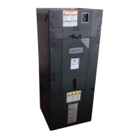
Trane GAM5 Series - User Manual

Trane GAM5 Series
40 pages
To Next Page IconTo Next Page
Loading...
18-GJ04D1-2
ALL phases of this installation must comply with NATIONAL, STATE AND LOCAL CODES
Important: This Document is customer property and is to remain with this unit. Please return to service information
pack upon completion of work.
These instructions do not cover all variations in systems
nor provide for every possible contingency to be met in
connection with the installation. Should further informa-
tion be desired or should particular problems arise which
are not covered sufficiently for the purchaser’s purposes,
the matter should be referred to your installing dealer or
local distributor.
Note: The manufacturer recommends installing ONLY
A.H.R.I. approved, matched indoor and outdoor systems.
Some of the benefits of installing approved matched
indoor and outdoor split systems are maximum efficien-
cy, optimum performance, and the best overall system
reliability.
Convertible Air Handlers
1-1/2 – 5 Ton
GAM5A0A18M11SAA
GAM5A0A24M21SAA
GAM5A0B30M21SAA
GAM5A0B36M31SAA
GAM5A0C42M31SAA
GAM5A0C48M41SAA
GAM5A0C60M51SAA
Note: Condensation may occur on the surface of the air
handler when installed in an unconditioned space. When
units are installed in unconditioned spaces, verify that
all electrical and refrigerant line penetrations on the air
handler are sealed completely.
The GAM5 air handlers will only use
the following internal electric heaters:
BAYEAAC05BK1AA
BAYEAAC05LG1AA
BAYEAAC08BK1AA
BAYEAAC08LG1AA
BAYEAAC10BK1AA
BAYEAAC10LG1AA
BAYEABC15BK1AA
BAYEABC20BK1AA
BAYEACC25BK1AA
Installer’s Guide
Question and Answer IconNeed help?

Do you have a question about the Trane GAM5 Series and is the answer not in the manual?

Trane GAM5 Series Specifications

General IconGeneral
TypeAir Handler
SeriesGAM5
Refrigerant CompatibilityR-410A
Voltage208/230V
PhaseSingle
Nominal Cooling Capacity1.5 to 5 tons
Cabinet ConstructionGalvanized steel
Heating CapacityVaries by model
Airflow ConfigurationUpflow, Downflow, Horizontal
Sound LevelVaries by model
Motor TypeVariable Speed

Summary

Section 1. Safety Information

General Safety Warnings and Hazards

Essential warnings for electrical, vapor, sharp edge, and corrosion hazards.

Cabinet Handling and Modification Precautions

Precautions against corrosion and improper cabinet modification or puncturing.

Section 2. Unit Design

2.1 Cabinet Penetration Guidelines

Specifies allowed locations for screws and cuts on the unit cabinet.

2.2 Access Panel Removal Procedures

Instructions for removing blower/filter and other access panels.

Section 3. Unit Preparation

3.1 Pre-Installation Unit Checks

Steps for checking unit for damage and verifying pressurization.

3.2 Available Unit Accessories

Lists compatible accessories and their cabinet size fit.

Section 4. Optional Cabinet Disassembly

4.1 Disassembly for Tight Spaces

Steps for disassembling the cabinet for installation in confined areas.

Section 5. Place Unit at Location

5.1 Approved Unit Carrying Methods

Demonstrates safe and approved methods for lifting and transporting the unit.

Section 6. Unit Location Considerations

6.1 Unit Dimensions and Weight

Provides physical dimensions and weights for various models.

6.2 Four-Way Conversion

Explains the unit's ability to be configured for upflow, downflow, and horizontal orientations.

6.3 Non Ducted Applications

Details considerations for installing the unit in non-ducted return configurations.

6.4 Ducted Applications

Details considerations for installing the unit in ducted return configurations.

6.5 Additional Unit Preparation Considerations

Covers important considerations like outdoor installation, accessories, and mobile home suitability.

Section 7. Setting the Unit - Vertical Installation

7.1 Considerations

Specifies minimum clearances and foundation requirements for vertical setup.

7.2 Upflow Installation

Details steps for assembling and positioning the unit for upflow configurations.

7.3 Downflow Installation

Outlines steps for preparing the site and setting the unit for downflow configurations.

Section 8. Setting the Unit - Horizontal Installation

8.1 Secure Coil (Horizontal Applications Only)

Instructions on how to secure the coil assembly for horizontal orientation.

8.2 Considerations

Guidelines for supporting the unit and installing auxiliary drain pans.

Section 9. Connecting the Duct work

9.1 Duct Connection Considerations

Covers connection methods, sealing, insulation, and specific kit requirements.

Section 10. Refrigerant Line

10.1 Refrigerant Line Connection Sizes

Table detailing vapor and liquid line connection sizes for various models.

10.2 Refrigerant System Layout

Diagram showing key refrigerant components like EEV, sensors, and valves.

Section 11. Refrigerant Line Brazing

11.1 Braze The Refrigerant Lines

Detailed procedures for preparing and brazing refrigerant lines.

Section 12. Condensate Drain Piping

12.1 Condensate Drain Piping Considerations

Compliance with codes, routing, slope, and fitting recommendations.

12.2 Connect Condensate Drain Piping

Step-by-step instructions for connecting primary and secondary drain lines.

Section 13. Electrical - Low Voltage

13.1 Low Voltage Maximum Wire Length

Table specifying maximum permissible lengths for low voltage wiring.

13.2 Low Voltage Hook-up Instructions

Procedures for connecting control wiring, including horizontal installation and refrigerant switch settings.

Section 14. Electrical - High Voltage

14.1 High Voltage Power Supply

Guidelines for matching power supply to equipment nameplate and code compliance.

14.2 Make Electrical Connections

Procedures for routing and connecting high voltage wiring to the unit.

Section 15. Time Delay Switch Adjustment

15.1 Remove the blower door panel.

Steps to remove the blower/filter panel for access.

15.2 Time Delay Relay (TDR) Switch

Instructions for adjusting the fan off delay setting on the TDR.

Section 16. Filters

16.1 Filter Considerations

Importance of filter installation and recommendations for maintenance access.

16.1 Filter Size Specifications

Table specifying filter sizes based on cabinet size.

Section 17. Unit Outline Drawing

17.1 Unit Dimensions and Clearances Diagram

Diagram and table showing unit dimensions and required clearances.

Section 18. Start Up

18.1 System Charge Adjustments

Tables detailing system charge based on indoor/outdoor unit combinations for rated HSPF.

18.2 System Start Up

Steps to ensure panels are secure, thermostat is set, and power is applied.

Section 19. Sequence of Operation

19.1 Sequence of Operation

Explains system operation modes like Continuous Fan, Heat Pump, Cooling, and Electric Heating.

Section 20. Checkout Procedures

20.1 Operational And Checkout Procedures

A comprehensive checklist for verifying proper installation and system operation.

Related product manuals