EasyManua.ls Logo

Trane GAM5A0B30M21SAA - User Manual

Trane GAM5A0B30M21SAA
40 pages
To Next Page IconTo Next Page
Loading...
18-GJ04D1-2
ALL phases of this installation must comply with NATIONAL, STATE AND LOCAL CODES
Important: This Document is customer property and is to remain with this unit. Please return to service information
pack upon completion of work.
These instructions do not cover all variations in systems
nor provide for every possible contingency to be met in
connection with the installation. Should further informa-
tion be desired or should particular problems arise which
are not covered sufficiently for the purchaser’s purposes,
the matter should be referred to your installing dealer or
local distributor.
Note: The manufacturer recommends installing ONLY
A.H.R.I. approved, matched indoor and outdoor systems.
Some of the benefits of installing approved matched
indoor and outdoor split systems are maximum efficien-
cy, optimum performance, and the best overall system
reliability.
Convertible Air Handlers
1-1/2 – 5 Ton
GAM5A0A18M11SAA
GAM5A0A24M21SAA
GAM5A0B30M21SAA
GAM5A0B36M31SAA
GAM5A0C42M31SAA
GAM5A0C48M41SAA
GAM5A0C60M51SAA
Note: Condensation may occur on the surface of the air
handler when installed in an unconditioned space. When
units are installed in unconditioned spaces, verify that
all electrical and refrigerant line penetrations on the air
handler are sealed completely.
The GAM5 air handlers will only use
the following internal electric heaters:
BAYEAAC05BK1AA
BAYEAAC05LG1AA
BAYEAAC08BK1AA
BAYEAAC08LG1AA
BAYEAAC10BK1AA
BAYEAAC10LG1AA
BAYEABC15BK1AA
BAYEABC20BK1AA
BAYEACC25BK1AA
Installer’s Guide
Question and Answer IconNeed help?

Do you have a question about the Trane GAM5A0B30M21SAA and is the answer not in the manual?

Trane GAM5A0B30M21SAA Specifications

General IconGeneral
Model NumberGAM5A0B30M21SAA
CategoryAir Handlers
Nominal Cooling Capacity2.5 tons
Voltage208/230V
Phase1
Motor TypePSC
Depth21 inches
Shipping Weight120 lbs
Maximum Fuse Size15 A
InsulationFoil-faced
Filter TypeStandard
Drain Connection3/4 inch
Nominal Heating Capacity30000 BTU

Summary

Section 1. Safety Information

Section 3. Unit Preparation

3.1 Prepare The Unit For Installation

Instructions for initial unit inspection and preparation before installation.

Section 7. Setting the Unit - Vertical Installation

Section 8. Setting the Unit - Horizontal Installation

Section 9. Connecting the Duct work

9.1 Duct Connection Considerations

Guidelines for properly connecting supply and return air ducts to the unit.

Section 10. Refrigerant Line

10.1 Refrigerant Line Connection Sizes

Table showing required refrigerant line sizes for different models.

Section 11. Refrigerant Line Brazing

11.1 Braze The Refrigerant Lines

Step-by-step instructions for brazing refrigerant line connections.

Section 12. Condensate Drain Piping

Section 13. Electrical - Low Voltage

13.2 Low Voltage Hook-up Instructions

Step-by-step guide for connecting low voltage wiring to the unit.

Section 14. Electrical - High Voltage

14.2 Make Electrical Connections

Instructions for making high voltage electrical connections to the unit.

Section 18. Start Up

18.1 System Charge Adjustments

Guidelines for charging the system to maintain rated HSPF.

18.2 System Start Up

Steps for powering up and starting the installed system.

Section 20. Checkout Procedures

20.1 Operational And Checkout Procedures

A checklist for verifying correct installation and operation.
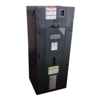
Related product manuals