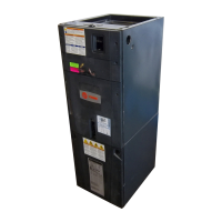
Do you have a question about the Trane GAF2A0A36S31EE and is the answer not in the manual?
Essential safety advisories regarding electrical hazards, vapors, corrosion, sharp edges, and chemical exposure.
Specifies approved locations for screws and penetrations on the unit cabinet for wiring and accessories.
Step-by-step guide to removing the unit's four access panels using a Phillips head screwdriver.
Procedures for checking unit condition, transport positioning, and initial setup before installation.
Lists accessory part numbers, descriptions, and cabinet compatibility for heaters, flanges, and kits.
Instructions on how to disassemble the unit cabinet, including removing panels and blower assembly.
Details the correct methods for lifting and transporting the air handler to its installation site.
Provides a table with model numbers, dimensions (H x D x W), and net weights in pounds.
Explains how to orient the air handler for upflow, horizontal right, or horizontal left airflow configurations.
Table detailing minimum clearances to combustible materials and recommended service clearances.
Safety precautions and installation advice for units without a return air duct, including vapor hazards.
Recommendations for installing units with ducted supply and return air in attics, garages, or crawl spaces.
Covers noise mitigation, local codes, accessory placement, and unit certifications like UL and mobile home suitability.
Specifies minimum height and front clearances required for proper airflow and maintenance.
Instructions for installing the unit in an upflow configuration using TASB or plenum methods.
Key considerations for horizontal mounting, including bottom support, leveling, and auxiliary drain pan requirements.
Guidelines for connecting supply and return ducts, sealing, insulation, and using flange kits or side returns.
Table detailing vapor and liquid line connection sizes for various models and system layout diagram.
Step-by-step guide for brazing refrigerant lines, emphasizing protection of sensitive components like the TXV bulb.
Considerations for drain plumbing, routing, slope, and connecting for upflow and horizontal orientations.
Table specifying maximum allowable lengths for low voltage wiring based on wire gauge size.
Instructions for routing and connecting low voltage wiring, including drilling entry points and strain relief.
Guidelines for matching the high voltage power supply to the equipment nameplate and complying with codes.
Procedures for routing high voltage wiring, connecting conduit, and wiring for electric heaters.
Discusses the need for remote filters and lists available bottom and front return filter kits with their sizes.
Provides detailed unit dimensions, outline drawings, and minimum clearance requirements.
Details system charge adjustments for specific matched indoor/outdoor units, referencing nameplate instructions.
Step-by-step guide to setting the thermostat and applying power to start the system.
Describes the operational sequences for continuous fan, heatpump, cooling, and electric heating modes.
A comprehensive checklist of operational and checkout procedures to ensure proper system performance after installation.
| Brand | Trane |
|---|---|
| Model | GAF2A0A36S31EE |
| Category | Air Handlers |
| Language | English |


 Loading...