20
8.2 Considerations
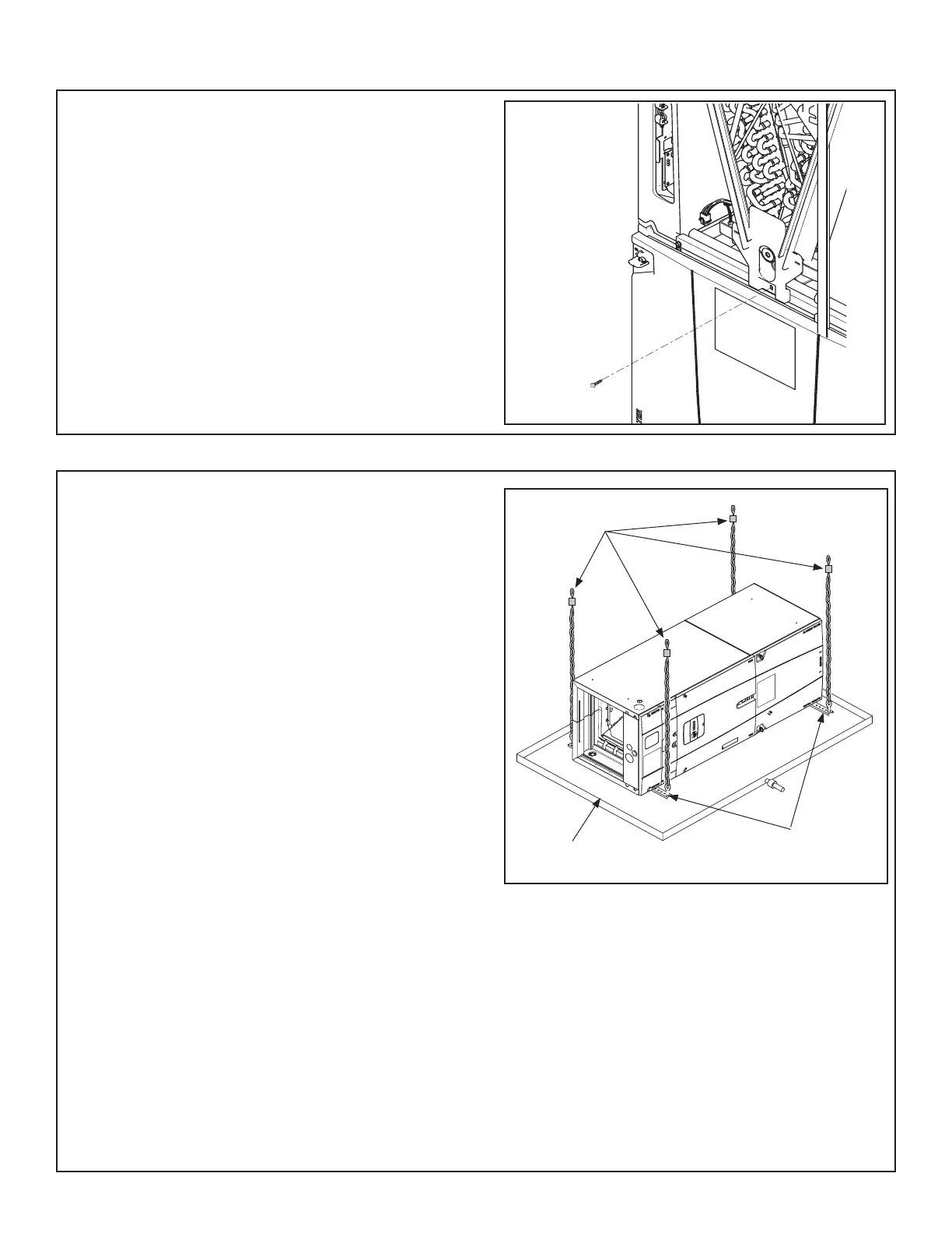
STEP 1 - Support the unit from the bottom (near both
ends). The service access must remain unobstructed.
Important: The unit can only be supported from the
bottom. Do not drill or screw supports into any area
of the cabinet.
Note: Do not allow the unit to be used as strain relief.
Approved bottom support methods are rails, u- •
channels (Unistrut®), or other load bearing materi-
als.
The unit must be isolated carefully to prevent •
sound transmission. Field supplied vibration isola-
tors are recommended.
STEP 2 - Install an auxiliary drain pan under the
horizontal air handler to prevent possible damage to
ceilings.
Isolate the auxiliary drain pan from the unit and •
from the structure.
Connect the auxiliary drain pan to a separate drain •
line and terminate according to local codes.
Important: Due to the unique design of this unit,
which allows the electrical wiring to be routed within
the insulation, do not screw, cut, or otherwise puncture
the unit cabinet in any location other than the ones
illustrated in this Installer Guide or in an approved ac-
cessory’s Installer Guide.
Important: Under no conditions should metal strap-
ping be attached to the unit to be used as support
mechanisms for carrying or suspension purposes.
Field Supplied
Isolators
Auxiliary Drain
Pan
Bottom Support
Near Both Ends
Section 8. Setting the Unit - Horizontal Installation
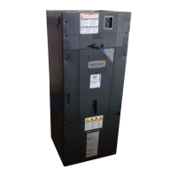
8.1 Secure Coil (Horizontal Applications Only)
STEP 1 - Remove Coil Panel.
STEP 2 - Remove screw from documentation packet.
STEP 3 - While the air handler is in the upflow posi-
tion, use the supplied screw to secure the coil seal
plate to cross member as shown.
Important: The Coil Seal Plate and screw secure the
coil in the center of the air handler. Failure to follow
these steps can prevent the Coil Panel from being eas-
ily replaced on the unit.