22
L8V1-SVX001-1A-EN
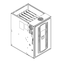
Furnace in horizontal right orientation with gas piping out top
Ground
Union Joint
Drip Leg
1/8” NPT
Test Fitting
Main Manual
Shut-o Valve
Automatic Gas Valve
with Manual Shut-o
Furnace in horizontal right orientation with gas piping out bottom
Note: For ease of installation, optional accessory part PIP02095 is
recommended for gas piping entering the bottom of the
furnace in the horizontal right position.
Automatic Gas Valve
with Manual Shut-o
Ground
Union
Joint
Drip Leg
1/8” NPT
Test Fitting
Main Manual
Shut-o Valve
The furnace is shipped standard for left side installation of gas piping.
A cutout with plug is provided on the right side for an alternate gas
piping arrangement.
The installation of piping shall be in accordance with piping codes and
the regulations of the local gas company. Pipe joint compound must be
resistant to the chemical reaction with liquefied petroleum gases.
Important: If local codes allow the use of flexible gas appliance
connector, always use a new listed connector. Do not use
a connector which has previously serviced another gas
appliance.
Refer to the piping table for delivery sizes. Connect gas supply to the
unit, using a ground joint union and a manual shut-off valve. National
codes require a condensation drip leg to be installed ahead of the gas
valve.
The furnace and its individual shut-off valve must be disconnected
from the gas supply piping system during any pressure testing of that
system at test pressures in excess of 1/2 psig (3.5 kPa).
The furnace must be isolated from the gas supply piping by closing its
individual manual shut-off valve during any pressure testing of the
gas supply piping system at test pressures equal to or less than 1/2
psig (3.5 kPa).
Note: Maximum pressure to the gas valve for natural gas is 13.8" W.
C. Minimum pressure is 5.0" W.C.
NATURAL GAS ONLY
TABLE OF CUBIC FEET PER HOUR OF GAS
FOR VARIOUS PIPE SIZES AND LENGTHS
PIPE
SIZE
LENGTH OF PIPE
10 20 30 40 50 60 70
1/2 131 90 72 62 55 50 46
3/4 273 188 151 129 114 104 95
1 514 353 284 243 215 195 179
1–1/4 1060 726 583 499 442 400 368
This table is based on Pressure Drop of 0.3 inch W.C. and 0.6 SP.
GR. Gas
All gas fittings must be checked for leaks using a soapy solution before
lighting the furnace. DO NOT CHECK WITH AN OPEN FLAME!
ORIFICE SIZES
INPUT
RATING
BTUH
NUMBER OF
BURNERS
MAIN BURNER ORIFICE
DRILL SIZE
NAT. GAS
40,000 1 1 - 3.2 mm
60,000 1 1 - #23
80,000 1 1 - #15
100,000 1 1 - #11
FFuurrnnaaccee GGeenneerraall IInnssttaallllaattiioonn