32
L8V1-SVX001-1A-EN
Table 12. Return Duct Connections (continued)
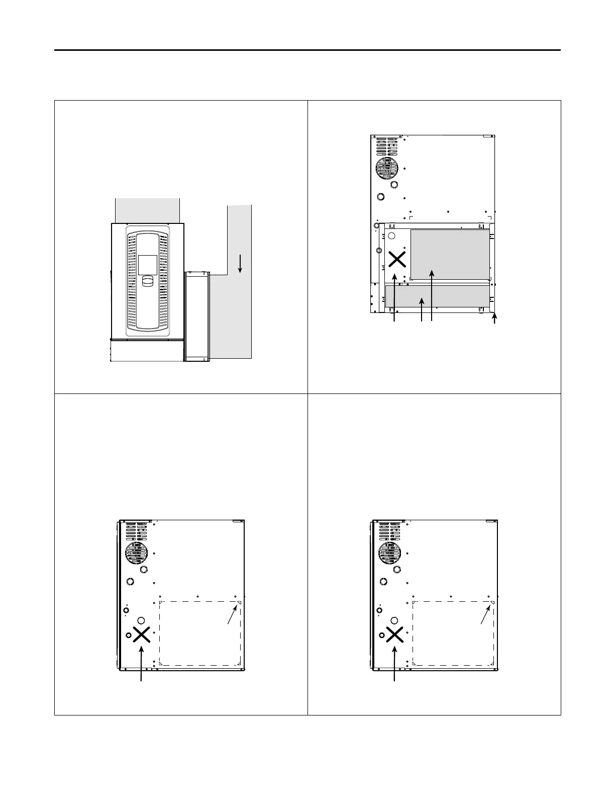
Upflow Furnace with Bottom and Side Returns Mounted on a
Ducted Pedestal with Side Return and Filter Box
Important: Make sure the thermostat wiring hole is sealed on the
cabinet side with the side return.
Important: Make sure not to cut the cabinet in the “No Cut” area.
Note: Use Optional BAYLIFT kit to lift furnace. Follow kit instructions.
Note: The furnace bottom pedestal must be a minimum of 6” in
height.
Cabinet cutout when used with BAYLIFT
No Cut Area Cutouts
21” Filter Cabinet with BAYLIFT Kit shown
Flush with back
of furnace cabinet
Refer to Step 1. Step 10. Step 11. Step 12. Step 13. Step 14. Step 15.
Step 4.
Upflow Furnace with Side Return
Important: Make sure the thermostat wiring hole is sealed on the
cabinet side with the side return.
Important: Make sure not to cut the cabinet in the “No Cut” area.
Note: If using a filter box, use a transition, if possible, to attach the
filter box to the furnace cabinet.
Upflow Furnace with Two Side Returns
Important: One of the sides must have a transition to allow the
thermostat wiring to exit the cabinet.
Important: If a transition is not a viable option, a hole will need to be
drilled in the side of the cabinet for the thermostat wiring
to exit.
Important: Make sure not to cut the cabinet in the “No Cut” area.
Note: If using one transition, the thermostat wiring will exit on the
transition side.
Note: If using a filter boxes, use transitions, if possible, to attach the
filter boxes to the furnace cabinet.
Use four corner guides
to create cutout
No Cut Area
Refer to Step 16. Step 17. Step 18. Step 19.
Use four corner guides
to create cutout
No Cut Area
Refer to Step 16. Step 17. Step 18. Step 19.
FFuurrnnaaccee GGeenneerraall IInnssttaallllaattiioonn