32 LPC-SVX01C-EN
mechanical
requirements
Installation
Coil Connection Recommendations
Follow these recommendations to
prevent possible damage when making
coil connections:
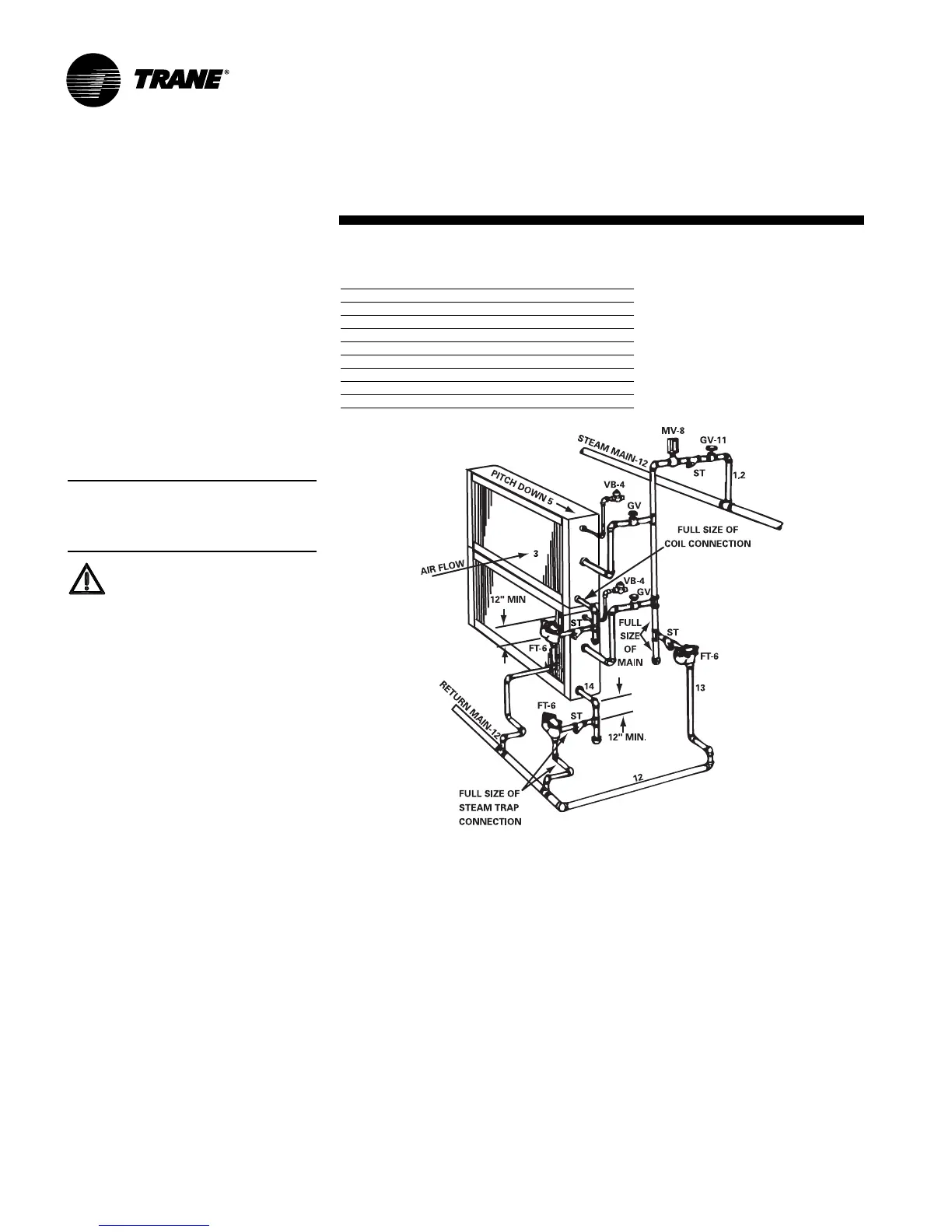
1. Install a ½”15 swing-check vacuum
breaker in the unused condensate
return connection at the top of the
coil. Install this vacuum breaker as
close to the coil as possible.
2. Vent the vacuum breaker to the
atmosphere or pipe it to the return
main at the discharge side of the
steam trap.
Note: A vacuum breaker is mandatory
when the coil is controlled by a modulat-
ing steam supply or two-position (on/off)
automatic steam supply valve.
WARNING
Hazardous Pressures!
If a heat source is required to raise
the tank pressure during removal of
refrigerant from cylinders, use only
warm water or heat blankets to raise
the tank temperature. Do not exceed
a temperature of 150
°
F. Do not, under
any circumstances apply direct
flame to any portion of the cylinder.
Failure to follow these safety pre-
cautions could result in a violent ex-
plosion, which could result in death
or serious injury.
The condensate return line must be
piped full size of the condensate trap
connection, except for a short nipple
screwed directly into the coil headers
condensate return trapping. Do not bush
or reduce the coil return tapping size.
Proper Steam Trap Installation
Proper steam trap selection and
installation is necessary for satisfactory
coil performance and service life. For
installation, use the following steps:
1. Install the steam trap discharge 12
inches below the condensate return
connection to provide sufficient head
pressure to overcome trap losses
and ensure complete condensate
removal. Use float and themostatic
traps with atmospheric pressure
gravity condensate return, with
automatic controls or when there is a
possibility of low pressure steam.
Float and thermostatic traps are
recommended because gravity drain
and continuous discharge operation.
2. Trap each coil separately to prevent
holding up condensate in one or
more of the coils.
3. Install strainers as close as possible
to the inlet side of the trap.
4. Use a V-Port modulating valve to
obtain gradual modulation of the coil
steam supply.
5. Do not modulate systems with
overhead or pressurized returns
unless the condensate is drained by
gravity into a receiver, vented to
atmosphere, and returned to the
condensate pump.
Figure I-MR-2. Typical Piping for Steam Coils
Code of System Components in Piping Diagram
FT Float and thermostatic steam trap
BT Bucket steam trap
GV Gate valve
OV Automatic two-position (on-off) control valve
TV Automatic three-way control valve
VB Vacuum breaker
CV Check valve
ST Strainer
AV Automatic or manual air vent
6. Slowly turn the steam on full for at
least ten minutes before opening the
fresh air intake on units with fresh air
dampers.
7. Pitch all supply and return steam
piping down 1-inch per 10 feet in the
direction of the steam or condensate
flow.
8. Do not drain the steam mains or
take-offs through the coils. Drain the
mains ahead of the coil through a
steam trap to the return line.
9. Assure continuous condensate
removal. Overhead returns require
one psig of pressure at the steam
trap discharge for each two feet of
elevation.