LPC-SVX01C-EN 51
Operation
general
information
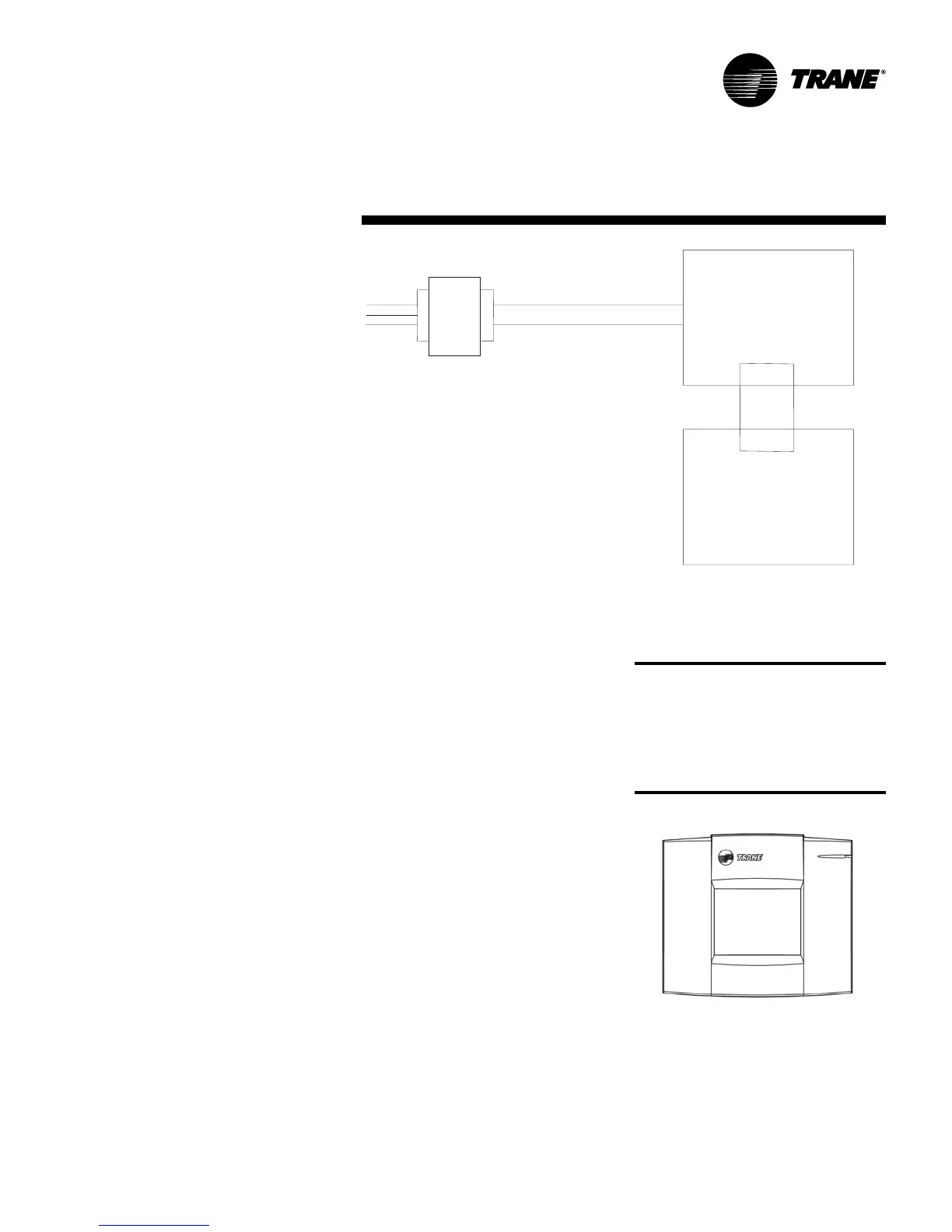
Figure O-GI-10. Power requirements
Operator display
This section explains how to install a
Tracer AH540/541 operator display and
set up the operator display.
Installing the stand-alone operator
display
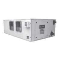
With the attached cable, the stand-alone
operator display (see Figure O-GI-11)
can be mounted up to 10 ft (3 m) from the
Tracer AH541 controller. You can extend
this distance up to 150 ft (46 m) using
four-conductor wire and the included pig-
tail connectors. Alternately, use three
twisted-pair wires. Trane recommends
the following four-conductor wires:
• Plenum 18 AWG, Trane part number
400-2059
• Plenum 22 AWG, Trane part number
400-2020
• Non-plenum, Trane part number 400-
1005
Figure O-GI-11. Tracer AH541 stand-alone
operator display
CAUTION
Avoid
Equipment Damage!
To
clean the operator display, use a cloth
dampened with commercial liquid
glass cleaner. Spraying water or
cleansers directly on the screen may
result in equipment damage.
Termination board
Main controller board
Transformer
Line
voltage
24 Vac