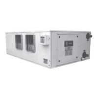
The Trane Low Height Air Handler (LWHA_ME) is a versatile air handling unit designed for installation, operation, and maintenance in various commercial and industrial settings. It is available in both belt-drive and direct-drive configurations, offering flexibility to suit different application requirements. The belt-drive models include 013-133, while the direct-drive models are 013-053.
Function Description
The LWHA_ME air handler is designed to provide conditioned air, contributing to a comfortable and controlled indoor environment. It integrates essential components such as coils (cooling and heating), a fan section, and filters to process and deliver air. The unit can be configured with different coil types (e.g., 3-row, 4-row, 5-row, 6-row, 4+1 row, 6+1 row) and fan motor types (e.g., 1-phase, 3-phase, 2-pole, 4-pole, 6-pole) to meet specific performance demands.
The unit's primary function involves drawing in return air, filtering it, conditioning it through the coils (cooling or heating), and then distributing the treated air back into the space. The fan section, driven by either a belt or directly by a motor, is responsible for moving the air through the unit and into the ductwork system. The unit can also incorporate a field-installed auxiliary drain pan to manage condensate effectively.
Important Technical Specifications
The LWHA_ME series offers a wide range of models with varying dimensions, capacities, and electrical characteristics.
Model Number Breakdown (KAEC Version):
The model number provides detailed information about the unit's configuration:
- Digit 1 (L): Low Height
- Digit 2 (W): Washable
- Digit 3 (H): High Static
- Digit 4 (A): Air Handler
- Digits 5,6,7 (013-133): Unit Size (e.g., 013, 020, 023, 033, 043, 053, 063, 083, 113, 133)
- Digit 8 (K): Minor Design Sequence
- Digit 9 (1): Fan Motor Drive (1=Belt Drive, 2=Belt Drive, 3=Belt Drive, 4=Belt Drive, 5=Belt Drive, 6=Belt Drive, 7=Belt Drive, 8=Belt Drive, 9=Belt Drive, 0=Direct Drive)
- Digit 10 (A): Fan Motor kW (A=0.18, B=0.25, C=0.37, D=0.55, E=0.75, F=1.1, G=1.5, H=2.2, I=3.0, J=4.0, K=5.5)
- Digit 11 (D): Electrical Supply (D=400V 3Ph 50Hz, C=400V 3Ph 60Hz, B=220-240V 1Ph 50Hz, A=220-240V 1Ph 60Hz)
- Digit 12 (1): Fan Model (1=Belt Drive, 0=Direct Drive)
- Digit 13 (4): Coil Row (3=3 Row, 4=4 Row, 5=5 Row, 6=6 Row, 4+1=4+1 Row, 6+1=6+1 Row)
- Digit 14 (X): TURB Option (X=None, Y=Yes)
- Digit 15 (L): Coil Connection (L=Left, R=Right)
- Digit 16 (2): Filter Type (2=2" Washable, 0=2" DX79, X=None, S=Special)
- Digit 17 (E): Electric Heater (0=None, A=2.1kW 1ph, B=3.0kW 1ph, C=4.2kW 1ph, D=6.0kW 1ph, E=9.0kW 1ph, F=12.0kW 1ph, G=15.0kW 1ph, H=18.0kW 1ph, I=21.0kW 1ph, J=24.0kW 1ph, K=27.0kW 1ph, L=30.0kW 1ph, M=33.0kW 1ph, N=36.0kW 1ph, O=39.0kW 1ph, P=42.0kW 1ph, Q=45.0kW 1ph, R=48.0kW 1ph, S=51.0kW 1ph, T=54.0kW 1ph, U=57.0kW 1ph, V=60.0kW 1ph, W=63.0kW 1ph, X=66.0kW 1ph, Y=69.0kW 1ph, Z=72.0kW 1ph)
- Digit 18 (1): Drain Pan (1=GI, 2=Stainless Steel)
- Digit 19 (A): Future Use
- Digit 20 (A): Service Indicator (A=First Design)
Coil Specifications:
- CHW Coil: 1-1/2" BSPT (for models 013-133)
- HOTW Coil: 1-1/4" BSPT (for models 013-133)
- Coil connections are typically 3/4" or 1/2" copper tubes, depending on the unit size and configuration.
Electrical Data:
- Fan Motor: Available in various kW ratings (0.18 kW to 5.5 kW) and electrical configurations (220-240V 1Ph 50/60Hz, 400V 3Ph 50/60Hz).
- Electric Heater: Optional, with capacities ranging from 2.1 kW to 72.0 kW, available in 1-phase or 3-phase.
Dimensions:
The unit dimensions vary significantly by model. For example, a LWHA 013/020/023/033 LH Coil (3-row & 5-row) has a width (d1) of 650mm, a depth (d2) of 695mm, and a height (a1) of 600mm. Larger units like the LWHA 043/053/063/083/113/133 LH Coil (3-row & 5-row) can have a width (d1) of 1118mm, a depth (d2) of 695mm, and a height (a1) of 600mm. Detailed dimension tables are provided for various coil configurations (3-row, 4-row, 5-row, 6-row, 4+1 row, 6+1 row).
Filter Data:
- Standard filter size is 2" washable.
- Filter quantity varies by unit size (e.g., 2 filters for smaller units, 3 filters for larger units).
Usage Features
Installation:
- Unit Location: Designed for horizontal application only. Requires adequate power supply and sufficient space for airflow and maintenance.
- Mounting: Units can be suspended from the ceiling using threaded rods or mounted on a supporting structure. Proper vibration isolation is crucial, achieved through the use of spring-type vibration isolators.
- Coil Connections: Requires careful piping to prevent excessive noise and vibration. Straight ductwork of 1-1/2 to 2 times the fan diameter is recommended for optimal airflow.
- Condensate Drain: A properly sloped drain pan and U-trap are essential for effective condensate removal. The drain line should be at least 15mm below the unit's bottom.
- Auxiliary Drain Pan: A field-fabricated auxiliary drain pan is recommended to prevent water damage in case of primary drain line blockage or overflow.
- Duct Connections: The inlet and discharge air duct connections should incorporate flexible connectors to minimize noise and vibration.
Operation:
- Fan Motor: The unit can be configured with various fan motor types (e.g., 1-phase, 3-phase, 2-pole, 4-pole, 6-pole) to match specific airflow requirements.
- Electrical Wiring: Wiring diagrams are provided for both belt-drive and direct-drive fan motors, including options for field-provided starter systems and heater wiring. All electrical wiring must comply with local and national electrical codes.
- Controls: The unit can be integrated with a thermostat or other control systems for automatic operation.
Maintenance Features
Pre-Start-Up Inspection:
Before operating the unit, a thorough inspection is required:
- Verify secure mounting, proper wiring, and tight connections.
- Check that coils are clean and free from damage.
- Ensure condensate drain pan and lines are clear.
- Confirm fan motor, pulley, and belt alignment (for belt-drive units).
- Verify proper voltage and amperage.
- Check for any unusual noises or vibrations.
Regular Maintenance:
- Filter Cleaning/Change: Filters should be cleaned or replaced regularly (monthly or as needed) to maintain airflow and prevent dirt buildup. Washable filters can be cleaned with water and mild detergent.
- Fan Belt Tension (Belt-Drive Units): Belts should be checked monthly for tension and wear. Proper belt tension is critical to ensure maximum bearing and drive component life. A belt tension measurement tool is recommended. The deflection should be 10mm per meter of span.
- Fan Bearings: Bearings should be checked annually for lubrication and wear.
- Coil Cleaning: Coils should be cleaned annually or as needed to maintain heat transfer efficiency. Do not use harsh chemicals.
- Drain Pan and Lines: Inspect and clean the condensate drain pan and lines regularly to prevent blockages and overflow.
- Electrical Connections: Periodically check all electrical connections for tightness and signs of wear.
Trouble Analysis:
A comprehensive trouble analysis section helps diagnose and resolve common issues:
- Rapid motor bearing wear: Often caused by excessive overhung load or tension. Recommended action: check belt tension and overhung load, replace sheave if necessary.
- Loose fan belt: Leads to poor fan performance. Recommended action: adjust belt tension, replace belt, check sheave alignment.
- Short belt life: Caused by worn sheaves, misalignment, or grease/oil on belts. Recommended action: replace sheaves, realign drive, clean belts and sheaves, adjust tension.
- Bearing Noise: Indicates inadequate lubrication or poor alignment. Recommended action: lubricate bearing, loosen mounting bolts, and realign.
- Low coil capacity (Chilled Water): Can be due to inadequate lubrication, incorrect airflow, or clogged coils. Recommended action: check fan-operating conditions, check water pumps and lines for obstructions.
- Under CFM or low air flow: Often caused by loose belts, dirty filter, or duct leakages. Recommended action: adjust belt tension, clean filter, check duct joining or turning, increase fan rpm.
- Over CFM or high air flow: Can be due to oversized duct or dirty filter. Recommended action: replace pulley to reduce fan rpm.
- Water leaking: Caused by a choked drain pipe or improper/no U-trap. Recommended action: clear drain pipe, ensure U-trap is installed properly.
Safety Precautions:
- Always disconnect electrical power before performing any maintenance or service.
- Use caution when working near moving parts (fan impeller) to prevent injury.
- Ensure proper grounding of the unit.
- Follow all local and national electrical codes.
- Use appropriate personal protective equipment.