TRANE
®
TRANE
®
2
Low Height Air Handler
Unit Sizes
013 023 043 063 113
020 033 053 083 133
Minor Design Sequence:
K=First Design for LWHA_ME
Fan Drive Type / Motor MCLS,
1 = Belt Drive/IE
2 = Belt Drive/IE2
3 = Belt Drive/IE3
D = Direct Drive
Fan Motor kW. Refer Table
Electrical rating / Utilization Range : Volt/Phase/Hz.
B = 380V/ 3Ph/ 50Hz K = 400V/ 3Ph/ 60Hz
C = 400V/ 3Ph/ 50Hz H = 460V/ 3Ph/ 60Hz
D = 415V/ 3Ph/ 50Hz 5 = 220-240/ 1Ph/ 50Hz (For Direct Drive)
F = 380V/ 3Ph/ 60Hz
Fan Model
Coil Row 3 = 3 Row 4 = 4 Row 5 = 5 Row
6 = 6 Row 7 = 4+1 Row 8 = 6+1 Row
TURB Option X = None Y = Yes
Coil Connection L = Left R = Right
Filter Type 2=2” Washable, G3: EN779
X = None S = Special
Electric Heater
Drain Pan 1 = GI 2 = Stainless Steel
Future Use
Service Indicator, A = First Design
1
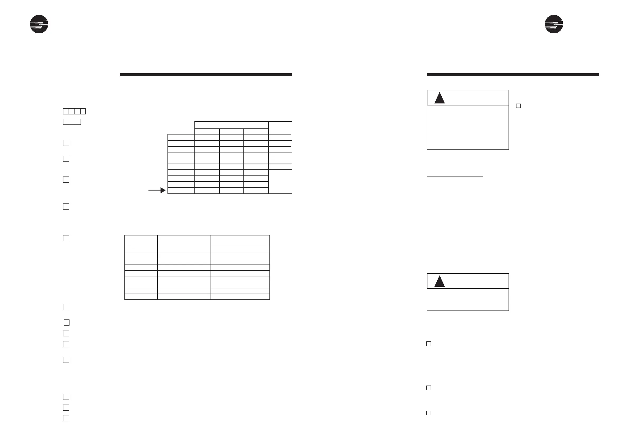
LWHA Model Number Description
(KAEC Version)
Digit 1,2,3,4
Digit 5,6,7
Digit 8
Digit 9
Digit 10
Digit 11
Digit 12
Digit 13
Digit 14
Digit 15
Digit 16
Digit 17
Digit 18
Digit 19
Digit 20
L W H A
013
K
1
A
D
1
4
X
L
2
0
1
0
A
LWHA013K1AD14XL2010A
1234567891011121314151617181920
LWHA 013
LWHA 020
LWHA 023
LWHA 033
LWHA 043
LWHA 053
LWHA 063
LWHA 083
LWHA 113
LWHA 133
Low Static
A=0.18
A=0.18
B=0.37
C=0.75
C=0.75
D=1.1
E=1.5
E=1.5
F=2.2
G=3.0
Std.Static
B=0.37
B=0.37
C=0.75
D=1.1
D=1.1
E=1.5
F=2.2
F=2.2
G=3.0
H-4.0
High Static
C=0.75
C=0.75
D=1.1
E=1.5
E=1.5
F=2.2
G=3
G=3
H=4.0
I=5.5
Direct
Drive
K=0.35
L=0.55
L=0.55
M=0.6
N=0.75
Q=1.55
BELT DRIVE
Model Belt Driven Direct Driven
LWHA 013
LWHA 020
LWHA 023
LWHA 033
LWHA 043
LWHA 053
LWHA 063
LWHA 083
LWHA 113
LWHA 133
1 = KAT 7-7 S
1 = KAT 7-7 S
2 = KAT 9-7 S
2 = KAT 9-7 S
3 = KAT 9-7 S2
4 = KAT 10-8 S2
4 = KAT 10-8 S2
5 = KAT 12-9 S2
6 = KAT 15-11 S2
6 = KAT 15-11 S2
E = KDD 9/7T 350W
L = KDD 9/7T 550W
F = KDD 9/9T 550W
G = KD2 9/7T 600W
H = KD2 9/7 750W
I = KD2 9/9 1550W
NA
NA
NA
NA
DO NOT LIFT THE UNIT WITHOUT
TEST-LIFTING FOR BALANCE AND
RIGGING. DO NOT LIFT THE UNIT
ABOVE PERSONNEL. FAILURE TO
OBSERVE THESE WARNINGS MAY
RESULT IN PERSONAL INJURY,
DEATH OR EQUIPMENT DAMAGE.
WARNING
!
CHECK THAT THE SUPPORTING
STRUCTURE IS STRONG ENOUGH
TO SUPPORT UNIT WEIGHT.
WARNING
!
Unit Installation
Unit Location Recommen-
dations
When selecting and preparing of the
unit operating location, consider the
following:
1. LWHA shall be installed for hori-
zontal application only.
2. Available power supply must agree
with electrical data on unit
nameplate.
3. Consider the weight of the unit .
4. Allow sufficient space for the recom-
mended clearances. Refer to
Figure 1.
5. Installer must provide suspension
rods (threaded) for ceiling mounted
unit.
6. All unit must be installed level.
7. Coil piping and condensate drain
requirements must be considered.
Allow room for proper ductwork and
electrical connections. Support all
piping and ductwork independently
of unit to prevent excess noise and
vibration.
Lifting / Rigging Recom-
mendations
Before preparing the unit for lifting,
estimate the approximate center of
gravity for lifting safety. Because of
placement of internal components, the
unit weight may be unevenly
distributed, with more weight in the coil
area. Before hoisting unit into position,
be sure that a proper rigging method
is used, with straps or slings and
spreader bars for protection and safety
during lifting. Always test-lift the unit to
determine exact unit balance and
stability before hoisting it to the
installation location.
MOUNTING
Unit Suspension - Typical
Use suspension mouting kit to isolate
the unit from structure. This is usually
accomplished through the use of
spring or rubber type vibration
isolators. The units are designed to be
suspended from ceiling on threaded
rod size 1/2”(M12), furnished by the
installing contractor. Four external
mounting lugs are provided at bottom
of the unit. The false ceiling opening
must be large enough for future
maintenance.
pan. Refer to drain trap sketch in the
piping section.
4. Connect the ductwork to the unit.
Auxiliary Drain Pan
A field fabricated auxiliary drain pan
may be installed under the unit, and
when condensate overflow may cause
damage. This drain pan will eliminate
any excess condensation that may be
due to extreme humidity or an
obstructed drain in the primary drain
pan. Drain lines from this pan must be
installed, but should not be connected
to the primary drain line from the unit.
Isolate the auxiliary drain pan from both
the air handler and the structure.
Air Filters
LWHAs are shipped with 2” Washable
filters installed in the unit as standard.
For filter dimension and quantity, refer
to General Specification. Filter loading
method is sliding type and accessible
from both sides.
Duct Connections
The Inlet and Discharge air duct
connections to the unit should be
made with a flexible material
minimizing noise and vibration.
Typically, about 3 inches(75mm) is
needed for this connection to rigid
ductwork.
Duct turns and transitions must be
made carefully to minimize air friction
losses. Avoid sharp turns and use
splitters or turning vanes when elbows
are necessary. Discharge (supply)
ductwork should run in a straight line,
unchanged in size or direction, for at
least a distance of 1-1/2 fan diameters
(see General Specification, for fan
diameter).
The return duct should be sized to the
same dimensions as the return inlet
the return inlet of the unit.
All ductwork should be properly
insulated to prevet condensation and
heat loss.
To install unit complete the
following:
1. Determine the unit mounting hole
dimensions. Prepare the hanger
rod isolator assemblies (provided
by installing contractor) and install
them in the selected area. Threaded
rods are recommended for leveling
the unit.
2. Hoist the unit to the suspension rods
and attaché with washers and lock
nut. Refer to figure 2, for specific
mounting details.
3. Level the unit for proper coil drainage
and condensate removal from drain
0 = None
A = 2.1kW, 1Step
B = 3kW, 1Step
C = 3.6kW, 1Step
D = 4.2kW, 1Step
E = 5.1kW, 1Step
F = 6.6kW, 1Step
G = 7.5kW, 1Step
H = 9.6kW, 1Step
I = 10.2kW, 1Step
J = 3kW, 2Step
K = 3.6kW, 2Step
L = 4.2kW, 2Step
M = 5.1kW, 2Step
N = 7.8kW, 2Step
O = 8.4kW, 2Step
P = 10.2kW, 2Step
Q = 12.6kW, 2Step
R = 13.2kW, 2Step
S = 15kW, 2Step
T = 17.4kW, 2Step
U = 20.4kW, 2Step
 Loading...