88 LPC-SVX01C-EN
Operation
sequence of
operation
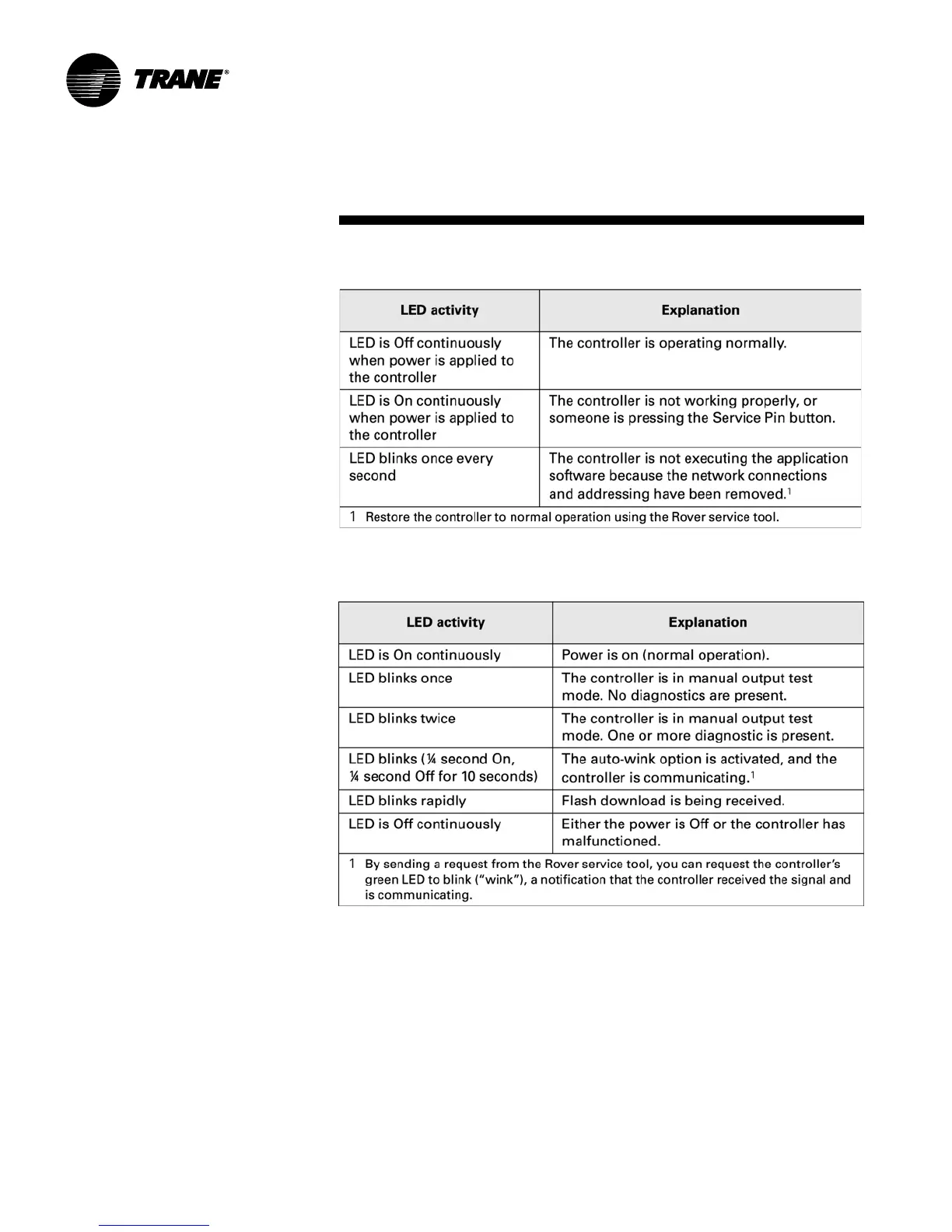
Service LED (red)
The Service LED indicates whether the
controller is operating normally.
Table O-SO-17 describes Service LED
activity.
Status LED (green)
The green Status LED indicates whether
the controller is receiving power
and if the controller is in manual test
mode. Table O-SO-18 describes Status
LED activity.
Comm LED (yellow)
The yellow Comm LED indicates the
communication status of the controller.
Table O-SO-19 describes Comm LED
activity.
Required inputs for unit operation
The following locally wired sensor or
communicated inputs are required
for each control function listed in Table O-
SO-20. If any one of the sensors does
not exist, the controller operates the
control function.
Table O-SO-17. Service LED (red)
Table O-SO-18. Status LED (green)