EasyManua.ls Logo

Trane Mitsubishi Electric CITY MULTI TPLFYP012EM140B User Manual

Trane Mitsubishi Electric CITY MULTI TPLFYP012EM140B
44 pages
To Next Page IconTo Next Page
Page #1 background imageLoading...
Page #1 background image
TECHNICAL & SERVICE MANUAL
Indoor unit
[Model Name]
CONTENTS
1. SAFETY PRECAUTION
..........................
2
2. PARTS NAMES AND FUNCTIONS
........
4
3. SPECIFICATIONS
.................................
12
4. 4-WAY AIRFLOW SYSTEM
..................
18
5. OUTLINES AND DIMENSIONS
............
21
6. WIRING DIAGRAM
...............................
22
7.
REFRIGERANT SYSTEM DIAGRAM
......
23
8. MICROPROCESSOR CONTROL
.........
24
9. TROUBLESHOOTING
..........................
31
10. DISASSEMBLY PROCEDURE
...........
39
INDOOR UNIT
PARTS CATALOG (OCBT746)
R410A
August 2020
No. OCHT746
REVISED EDITION-A
Grille model
[Model Name]
TLP-41EAEU
WIRED REMOTE
CONTROLLER
(Option)
IR WIRELESS REMOTE
CONTROLLER
(Option)
ON/OFF TEMP
MENU
ON
OFF
RETURN
SELECT
HOLD
Model name
indication for
MAIN UNIT
Model name
indication for GRILLE
TPLFYP006EM140B
TPLFYP008EM140B
TPLFYP012EM140B
TPLFYP015EM140B
TPLFYP018EM141B
TPLFYP024EM140B
TPLFYP030EM140B
TPLFYP036EM140B
TPLFYP048EM140B
INDOOR UNIT FOR VRF SYSTEM
Revision:
5.OUTLINES AND
DIMENSIONS has been
revised.
Some descriptions
have been modified
in
REVISED EDITION-A
.
OCHT746 is void.
Question and Answer IconNeed help?

Do you have a question about the Trane Mitsubishi Electric CITY MULTI TPLFYP012EM140B and is the answer not in the manual?

Trane Mitsubishi Electric CITY MULTI TPLFYP012EM140B Specifications

General IconGeneral
BrandTrane
ModelMitsubishi Electric CITY MULTI TPLFYP012EM140B
CategoryAir Conditioner
LanguageEnglish

Summary

Safety Precautions and Handling Guidelines

R410A Refrigerant Safety and Handling

Covers safe handling of R410A, proper tools, and general cautions for new refrigerant.

Service Tools and Refrigerant Charging

Details on specific tools for R410A, additional refrigerant charging procedures, and service cautions.

Unit Components and Remote Control

Indoor Unit Components Overview

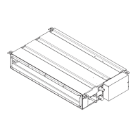
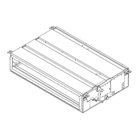
Identification of key parts of the indoor unit, such as sensors, vanes, and filters.

Wired Remote Controller Functions

Explanation of the wired remote controller's interface, buttons, and operational modes.

Technical Specifications and Performance Data

Model-Specific Technical Data

Detailed specifications for cooling/heating capacity, power, dimensions, and materials for each model.

Sound Pressure Level and NC Curves

Data on sound pressure levels and Noise Criteria (NC) curves for various operating conditions.

Electrical Parts Specifications

Specifications for internal electrical components like motors, thermistors, and fuses.

System Installation and Operational Modes

Airflow Direction and Ceiling Height Configuration

Guidance on setting air outlets and switches for optimal airflow based on ceiling height.

Refrigerant System Diagram and Pipe Sizes

Illustrates refrigerant flow and specifies pipe diameters for different models.

Microprocessor Control of Unit Operations

Details on Cool, Dry, Fan, Heat, and Auto operation modes controlled by the microprocessor.

Maintenance, Troubleshooting, and Disassembly

Component Testing and Troubleshooting Methods

Procedures for checking key components using a multimeter and diagnosing common issues.

DIP Switch Settings for Function Configuration

Explains the function and settings of various DIP switches for unit configuration.

Internal Component Disassembly Guide

Step-by-step instructions for safely removing and disassembling internal parts of the unit.

Related product manuals