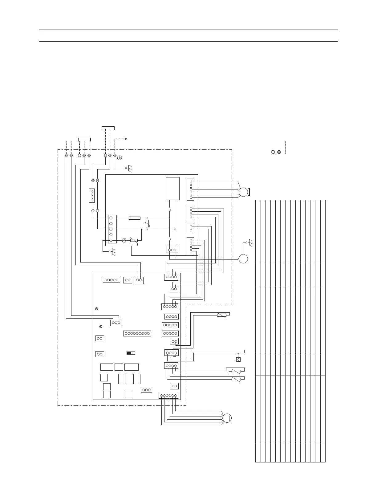
1. TPEFYP006, 008, 012, 015, 018, 024, 027, 030, 036, 048, 054MA143A
1
3
M
MS
3~
M
1~
4567112321
2
1
3
2
1
3
4
4
1
2
2
3
1
51
1
3
5
1
2
1
6
5
3
4
3
1
2
4
2
1
5
4
2
3
2
1
3214
2
1
4
INSIDE SECTION OF CONTROL BOX
I.B.
P.B.
LEV
Drainpump
Fan motor
U
(Red)
CN32
CN52
CN22
SWE
CN20
CN90
CN105
CN41
CN4F
CN51
CNXB2
CN2M
CNXC2
SW1
SWA
SW4
SW11
SW12
SW14
SWC
SW5
F01
DSA
ZNR02
CND
ZNR01
(Red)
CN44
(Green)
(Green)
(Blue)
TB2
POWER SUPPLY
AC 208/230V
60Hz
S(SHIELD)
DC280-340V
Rectifier
circuit
LED1
LED2
M2
M1
TB5
L2
G
L1
OFF
ON
X01
X10
CNXC1
CNP
CNMFCNXA1
ACL
CN27CN24
2
1
TH21
t°
SW3
CN2A
TB15
TH23
TH22
t° t°
FS
SW2
(Blue)
CNXA2
(Blue)
CN3A
(Blue)
(Black)
(Red)
(Blue)
(Red)(Yellow)
U
CN60
CNXB1
TO OUTDOOR UNIT
BC CONTROLLER
REMOTE CONTROLLER
TO MA REMOTE
CONTROLLER
NOTE:1.Symbols used in wiring diagram above are,
:Connector
:Terminal
(Heavy dotted line):Field wiring
2.Use copper supply wires.
Connector (0-10V Analog input)
Connector (IT terminal)
CN105
CN2A
Connector (HA terminal-A)
CN22
NAME NAME NAME
SYMBOL EXPLANATION
Power source terminal block
Transmission terminal block
TB5
TB2
SW4 (I.B.)
SW1 (I.B.)
SW14 (I.B.)
SW12 (I.B.)
SW11 (I.B.)
SW3 (I.B.)
SW2 (I.B.)Indoor controller board
I.B.
SYMBOL SYMBOL SYMBOL
TH22
TH23
Thermistor (inlet air temp.detection)
TH21
TB15
Transmission terminal block
CN41
CN27
CN51
CN32
CN52
CN24
Connector (Fan control)
Connector (Heater control)
CN90
Connector (Centrally control)
Connector (Remote switch)
Connector (Remote indication)
FS
Float switch
F01
Fuse AC250V 6.3A
ZNR01,02
Varistor
DSA
Arrester
Aux. relay
X01
Connector (Wireless)
SWA (I.B.)
SWC (I.B.)
SWE (I.B.)
ACL
AC reactor (Power factor improvement)
P.B.
Power supply board
X10
Aux. relay
LED1
LED2
LED (Power supply)
LED (Remote controller supply)
SW5 (I.B.)
Thermistor (piping temp.detection/liquid)
Thermistor (piping temp.detection/gas)
Switch (for mode selection)
Switch (for capacity code)
Switch (for mode selection)
Switch (for model selection)
Switch (for mode selection)
Switch (1s digit address set)
Switch (10ths digit address set)
Switch (connection No.set)
Switch (for static pressure selection)
Switch (for static pressure selection)
Connector (emergency operation)
Connector (Damper)
 Loading...