12 AMS-SVX03A-EN
Electrical control wiring
Indoor and outdoor unit communication wires specifi cation and
attention
Indoor and outdoor unit communication wires are provided by Trane. •
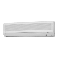
STP specifi cation is 0.5 ċ 1.25mm
2
and the lay is less than 10cm.
LLay ǘ 10cm
STP legend
ABC
D
A: Outer sheath B: Shield layer C: Insulator D: Conductor
Do not connect the power supply wire with the communication wire terminal.•
You have to connect control (communication) wire and the total length should be less than •
1,000m.
Shield layer of the communication wire and the main unit must be grounded.•
Install the communication wire before power on. Do not plug in and out with electricity, •
avoiding communication chip damage.
Control signal circuit must use STP, avoiding strong electric signal interference. (Choose •
network wire with tight shield layer and small lay.)
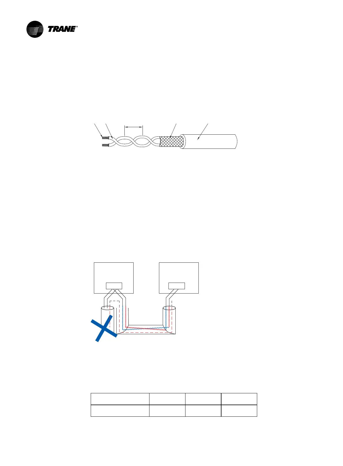
Control signal is divided into A and B, two polarities. Different polarities can •
not be connected as followings (A can not connect with B):
A1 B1
Communication port
Control main board
Communication port
Control main board
A1 B1
It is wrong to connect A with B.
When power supply wire and communication wire are parallel wiring, please cover •
conduits and keep a certain distance between them.
The communication wire passes through the side incoming hole and connects controller •
CN2 terminals as followings:
RS485 wire sequence A B Shield layer
CN2 terminal A B G
 Loading...