Do you have a question about the Trane MW(C)W509 and is the answer not in the manual?
Illustrates recommended clearance and mounting positions for the indoor unit installation.
Steps for securely mounting the hanging plate, ensuring it can withstand the unit's weight.
Guidance on drilling the correct size wall hole for piping and cable entry to prevent damage.
Instructions for correctly installing the drainage pipe, ensuring proper slope and insulation.
Guidelines for connecting refrigerant pipes, emphasizing careful bending and joint nut tightening.
Requirements for STP communication wires, grounding, and connection polarity between units.
DIP switch settings (S1-S4 on SW2) to define the indoor unit's cooling capacity (e.g., 2.8kW, 3.6kW).
How DIP switch S7 on SW2 controls the indoor fan speed to High/Medium/Low or Medium/Low/Extra-low.
Overview of the four LED lights (Heating, Dry, Cooling, Run) and their status indicators.
Detailed meanings of each LED state and how fault codes are displayed on the panel.
Step-by-step instructions for safely removing, cleaning, and reinstalling the unit's front panel.
How to remove and clean the air strainer, including recommended frequency and cleaning agents.
Checklist for ensuring unit readiness before the cooling/heating season begins.
Actions to take for unit shutdown and storage at the end of the service season.
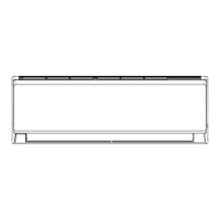
This document serves as the Installation & Operation Manual for the Trane Advanced Multi-split System Wall-mounted Indoor Unit, specifically models MW(C)W509/512/518, which operate with R410A refrigerant. It provides comprehensive instructions and important information for the proper installation, operation, and maintenance of these indoor units.
The Trane Advanced Multi-split System Wall-mounted Indoor Unit is designed to provide cooling and/or heating for indoor spaces as part of a multi-split air conditioning system. These units are wall-mounted, offering a space-saving and aesthetically pleasing solution for various room types. They are equipped with an electronic expansion valve (EXV) for precise refrigerant flow control, contributing to efficient operation. The system allows for multiple indoor units to operate simultaneously, connected to a single outdoor unit. The manual emphasizes that the total capacity of operating indoor units should not exceed the outdoor unit's capacity to ensure adequate cooling or heating performance.
The manual details the unit model nomenclature, breaking down each digit to represent specific features. For instance, "M" indicates a Trane mini split unit, "W" signifies a heat pump (or "C" for cooling only), and "W" denotes a wall-mounted unit. The nominal cooling capacity is indicated by digits 5 and 6 (e.g., 09, 12, 18, corresponding to 2.8kW, 3.6kW, and 5.0kW respectively). Power supply type is specified as M = 220~240V/50Hz/1PH. The units are designed without an electric heater ("N" for None) and come with an LCD remote controller ("C").
Electrical parameters are provided for models MW(C)W509, MW(C)W512, and MW(C)W518. All models operate at a frequency of 50Hz, with a rated voltage of 220~240V and a voltage range of 198~264V. The fan motor rated current (FLA) varies slightly by model: 0.23A for MW(C)W509 and 0.27A for MW(C)W512/518. The minimum line current is 0.30A for MW(C)W509 and 0.35A for MW(C)W512/518, with a copper core minimum diameter of 1.0mm² for all units.
Communication between indoor and outdoor units uses STP (Shielded Twisted Pair) wires with a specification of 0.5-1.25mm² and a lay of less than 10cm. The total length of the control (communication) wire should be less than 1,000m. The shield layer of the communication wire and the main unit must be grounded.
The remote controller offers a range of functions for user convenience. These include:
The unit features an LED display panel that indicates the operating mode (Cooling, Heating, Dry), run status (power supply), and displays numerical values for temperature or fault codes. For instance, a flashing fault indicator after 5 seconds signifies a mode conflict between indoor and outdoor units.
Regular maintenance is crucial for the unit's longevity and efficient operation. The manual provides detailed instructions for cleaning the panel and air strainer.
The manual also includes a "Fault analysis" section to help users troubleshoot common issues before contacting customer service, such as the unit not running, unusual smells or sounds, poor performance, or remote controller malfunctions. It advises against self-repair and recommends contacting Trane customer service for professional assistance.
| Brand | Trane |
|---|---|
| Model | MW(C)W509 |
| Category | Air Conditioner |
| Language | English |