EasyManuals Logo

Trane MWC518 User Manual

Trane MWC518
28 pages
To Next Page IconTo Next Page
To Previous Page IconTo Previous Page
Page #22 background imageLoading...
Page #22 background image
22 AMS-SVX02A-EN
Electrical Wiring Diagram
CN11
CN10
E
Yellow/green
M1
M2
AP2
CN3
FUSE:50T 3.15A 250V~
PCB
AP2
Wired controller
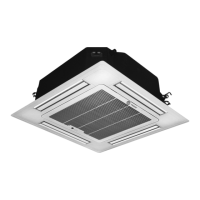
Cassette indoor unit
Yellow
Black
Blue
Red
White
Fan
Water pump
Power transformer
Evaporator
White
C
3
CN17
CN5
7
5
1
CN4
AP1
CN16
CN15
Communication wire
Communication wire
RT3
X201
TC
17 Yellow/green
Ambient
temperature
sensing bulb
Outlet
temperature
sensing bulb
Inlet
temperature
sensing bulb
Midpoint
temperature
sensing bulb
CN18
CN8
CN9
0
4
RT4
CN12
CN13
3
RT2
2
CN19
1
RT1
Power supply
CN2
3 Yellow/green
L
N
SA2
XT1
X4
22
Black
21Black
CN20
CN21
20Red
X3
19 White
Limit switch
BlackBlack
SA1
M3
Swing motor
Limit switch
CN1
61414396
Orange
9
0
0
0
L
L
2 Blue
1 Brown
CN7
EXV
Note: CN7 is screen printing of
main board electronic expansion
valve. Tie and fix external wire
of expansion valve. Do not touch
high temperature or wet objects.

Questions and Answers:

Question and Answer IconNeed help?

Do you have a question about the Trane MWC518 and is the answer not in the manual?

Trane MWC518 Specifications

General IconGeneral
BrandTrane
ModelMWC518
CategoryAir Conditioner
LanguageEnglish

Related product manuals