OPERATING PROCEDURE PHOTOS/FIGURES
(13)
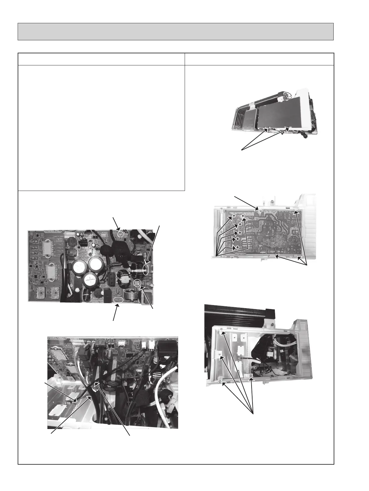
Disengage all the catches of the PB cover, and remove
the PB cover (Photo 9).
(14)
Remove the screw fixing the outdoor power P.C. board
and all the screws fixing the outdoor power P.C. board
and the heatsink (Photo 10).
(15)
Disengage all the catches of the outdoor power P.C.
board, and lift the outdoor power P.C. board (Photo 10).
(16)
While lifting the outdoor power P.C. board, disconnect
the lead wires, the connectors, and the earth wires; then
remove the outdoor power P.C. board (Photo 11).
NOTE: When reassembling, pass the lead wire of the
CN171 thorough the notch and behind the lead
wire of the compressor (Photo 12).
(17)
Remove all the screws of the heatsink fixing parts and
remove the heatsink fixing parts (Photo 13).
NOTE: Some units have only 1 heatsink fixing part.
(18)
Remove the heatsink.
100
Photo 11
Photo 12
Photo 13
Photo 10
Photo 9
Screws of the power
P.C. board and the
heatsink
Screw of the power
P.C. board
Catches of the
power P.C. board
Earth wires of TBE2, TBE4
Lead wire of CN171
Lead wire of compressor
Notch
Connetor
of CNAC1
Connetor of CN171
Lead wires of
TAB1, TAB2
Screws of fixing parts of the heat sink
Catches of PB cover
 Loading...