77
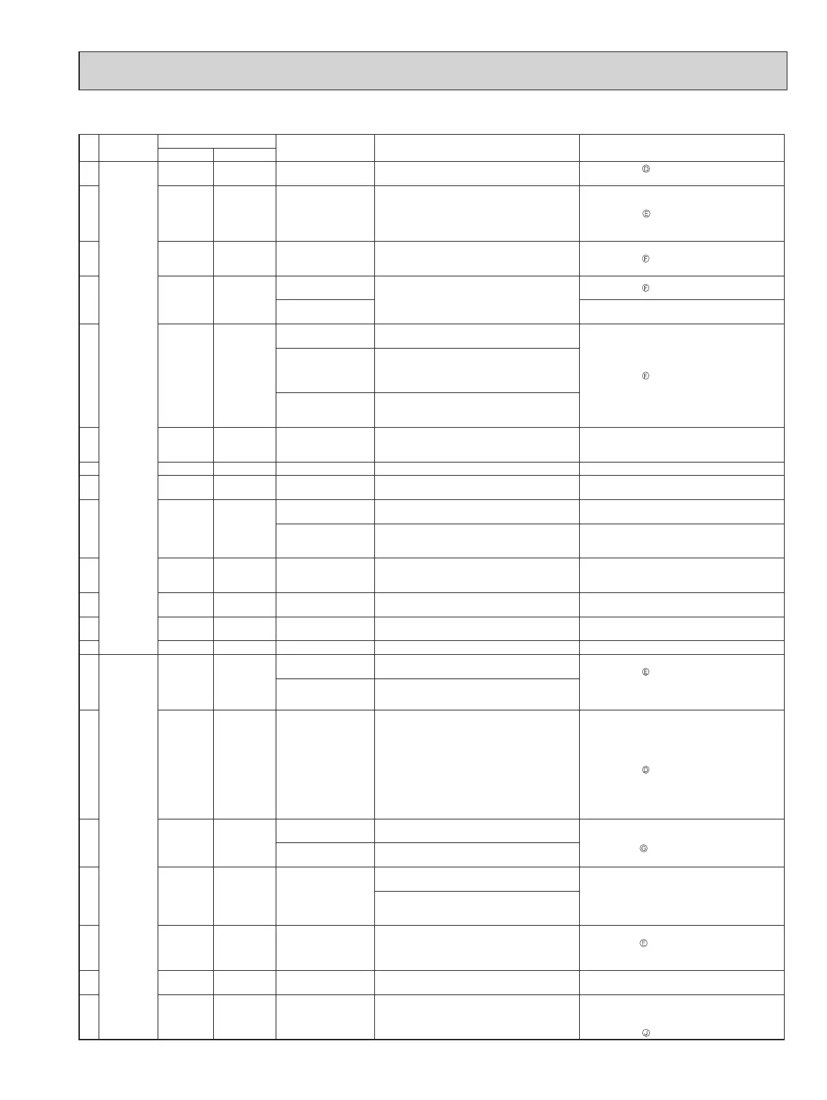
11-4. TROUBLESHOOTING CHECK TABLE
No. Symptom
Indication
Abnormal point / Con-
dition
Condition Remedy
LED1(Red) LED2(Yellow)
1 Outdoor
unit does
not operate.
Lit Once LEV and drain pump
The indoor unit detects an abnormality in the LEV
and drain pump.
• Refer to 11-6.
"Check of LEV".
• Check the drain pump of the indoor unit.
2
Lit Twice
Outdoor power
system
Overcurrent protection cut-out operates 3 consecu
-
tive times within 1 minute after the compressor
gets started, or converter protection cut-out or bus-
bar voltage protection cut-out operates 3 consecu
-
tive times within 3 minutes after startup.
• Ch
eck the connection of the compressor connect-
ing wire.
• Refer to 1
1-6.
"How to check inverter/compres-
sor".
• Check the stop valve.
3
Lit 3 times
Discharge temperature
thermistor
A
short circuit is detected in the thermistor during
operation, or an open circuit is detected in the
thermistor after 10 minutes of compressor startup.
• Refer to 11-6.
"Check of outdoor thermistors".
4
Lit 4 times
Fin temperature
thermistor
A short or open circuit is detected in the thermistor
during operation.
• Refer to 11-6.
"Check of outdoor thermistors".
P. C. board tempera-
ture thermistor
• Replace the outdoor control P
.C. board.
5
Lit 5 times
Ambient temperature
thermistor
A short or open circuit is detected in the thermistor
during operation.
• Refer to 11-6.
"Check of outdoor thermistors".
Outdoor heat ex-
changer temperature
thermistor
A
short circuit is detected in the thermistor during
operation, or an open circuit is detected in the
thermistor after 5 minutes (in cooling) and 10
minutes (in heating) of compressor startup.
Defrost thermistor
A short circuit is detected in the thermistor during
operation, or an open circuit is detected in the
thermistor after 5 minutes of compressor startup.
6
Lit 6 times
Zero cross detecting
circuit (Outdoor control
P.C. board)
Zero cross signal cannot be detected. • Replace the outdoor control P.C. board.
7 Lit 7 times Outdoor control system
The nonvolatile memory data cannot be read properly.
• Replace the outdoor control P.C. board.
8
Lit 8 times Current sensor
Current sensor protection cut-out operates 2 con-
secutive times.
• Replace the outdoor power P
.C. board.
9
Lit 11 times
Communication error
between P.C. boards
The communication protection cut-out between
boards operates 2 consecutive times.
• Check the connecting wire between outdoor con-
trol P.C. board and outdoor power P.C. board.
M-NET
communication
error
M-NET adapter P.C. board detects an abnormality
in the communication error.
• Check the connecting wire between M-NET
adapter P.C. board and outdoor control P.C.
board, or terminal bed.
10
Lit 12 times
Zero cross detecting
circuit (Outdoor power
P.C. board)
The protection cut-out of the zero cross detecting
circuit operates 10 consecutive times.
• Replace the outdoor power P.C. board.
11
Lit 13 times Current sensor
A short or open circuit is detected in the input cur
-
rent detection circuit during operation.
• Replace the outdoor power P
.C. board.
12
Lit 14 times Voltage sensor
A short or open circuit is detected in the input volt-
age detection circuit during operation.
• Replace the outdoor power P
.C. board.
13 Lit 15 times Relay operation No relay operation is detected during operation. • Replace the outdoor power P.C. board.
14 'Outdoor unit
stops and
restarts
3 minutes
later' is
repeated.
Twice Not lit
IPM protection
Overcurrent is detected after 30 seconds of com
-
pressor startup.
• Reconnect compressor connector
.
• Refer to 11-6. "How to check inverter/
compressor".
• Check the stop valve.
• Check the power module (PAM module).
Lock protection
Overcurrent is detected within 30 seconds of com
-
pressor startup.
15
3 times Not lit
Discharge temperature
protection
The discharge temperature exceeds
239°F (NTXMMX20A122AA)/222.8°F
(NTXMMX24A/30A132AA, NTXMMX36A142AA)/
240.8°F (NTXMMX42A152AA, NTXMPH20A122AA,
NTXMPH24A/30A132AA) during operation.
Compressor can restart if discharge temperature thermis
-
tor reads 176°F (NTXMMX20A122AA)/203°F
(NTXMMX24A/30A132AA, NTXMMX36A142AA)/212°F
(NTXMMX42A152AA, NTXMPH20A122AA,
NTXMPH24A/30A132AA) or less 3 minutes later.
• Check the amount of gas and refrigerant circuit.
• Refer to 11-6.
"Check of LEV".
16
4 times Not lit
Fin temperature
protection
The n temperature exceeds during operation.
•Check refrigerant circuit and refrigerant amount.
•Refer to 11-6.
"Check of outdoor fan motor".
P.C. board temperature
protection
The P.C. board temperature exceeds during opera-
tion.
17
5 times Not lit
High pressure
protection
High pressure is detected with the high pressure
switch (HPS) during operation.
• Check around of gas and the refrigerant circuit.
• Check the stop valve.
The outdoor heat exchanger temperature exceeds
158°F during cooling or the indoor gas pipe tem
-
perature exceeds 158°F during heating.
18
6 times Not lit Pre-heating protection Overcurrent is detected during pre-heating.
• Reconnect compressor connector
.
• Refer to 11-6.
"How to check inverter/
compressor".
• Check the power module.
19
8 times Not lit Converter protection
A failure is detected in the operation of the convert
-
er during operation.
• Replace the outdoor power P
.C. board.
20
9 times Not lit
Bus-bar voltage
protection
The bus-bar voltage exceeds 400 V or falls to low
level during compressor operating.
• Check the voltage of power supply.
• Replace the outdoor power P.C. board or the out
-
door control P.C. board.
• Refer to 1
1-6.
"Check of bus-bar voltage".
 Loading...