EasyManua.ls Logo

Trane NTXMMX36A142AA User Manual

Trane NTXMMX36A142AA
106 pages
To Next Page IconTo Next Page
Page #1 background imageLoading...
Page #1 background image
HFC
utilized
R410A
PARTS CATALOG (OBBT702)
SERVICE MANUAL
No. OBHT702
CONTENTS
1. TECHNICAL CHANGES ··································· 4
2. PART NAMES AND FUNCTIONS ····················· 5
3. SPECIFICATION ················································ 6
4. NOISE CRITERIA CURVES ···························· 14
5. OUTLINES AND DIMENSIONS ······················ 16
6. WIRING DIAGRAM ·········································· 22
7. REFRIGERANT SYSTEM DIAGRAM ············· 28
8. DATA ································································ 41
9. ACTUATOR CONTROL ··································· 70
10. SERVICE FUNCTIONS ···································· 71
11. TROUBLESHOOTING ····································· 73
12. DISASSEMBLY INSTRUCTIONS ···················· 94
Models
NTXMMX20A122AA
NTXMMX24A132AA
NTXMMX30A132AA
NTXMMX36A142AA
NTXMMX42A152AA
NTXMPH20A122AA
NTXMPH24A132AA
NTXMPH30A132AA
NTXMMX24A132AA
NTXMMX30A132AA
NTXMMX36A142AA
OUTDOOR UNIT
Indoor unit service manual
NTXWPH·A Series (OBHT683)
NTX(Y)WST·A Series (OBHT732)
NTXFKS·A Series (OBHT752)
NTXCKS·A Series (OCHT669)
PLA-A·EA Series (OCH640)
NTXDKS·A Series
PEAD-A·AA Series
PCA-A·KA Series (OCH455)
NTXAMT·A Series
Question and Answer IconNeed help?

Do you have a question about the Trane NTXMMX36A142AA and is the answer not in the manual?
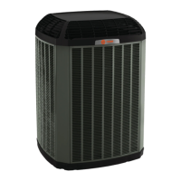
Trane NTXMMX36A142AA Specifications

General IconGeneral
ModelNTXMMX36A142AA
Cooling Capacity36000 BTU/H
Refrigerant TypeR-410A
Voltage208/230V
Phase1
SEER Rating17 SEER
Compressor TypeScroll

Summary

SERVICE MANUAL

SPECIFICATION

NOISE CRITERIA CURVES

WIRING DIAGRAM

REFRIGERANT SYSTEM DIAGRAM

MAX. REFRIGERANT PIPING LENGTH & PIPE SIZE SELECTION

DATA

SERVICE FUNCTIONS

AUTO LINE CORRECTING

Describes an automatic function to detect and correct improper wiring or piping.

TROUBLESHOOTING

Flow chart of the detailed outdoor unit failure mode recall function

Outlines the procedure to recall and interpret failure modes based on indicators.

Table of outdoor unit failure mode recall function

Lists failure modes, LED indications, conditions, and remedies for troubleshooting.

TROUBLESHOOTING CHECK TABLE

A detailed table correlating symptoms with LED indications, conditions, and remedies.

TROUBLE CRITERION OF MAIN PARTS

Provides resistance and voltage criteria for checking key component functionality.

How to check miswiring and serial signal error (when outdoor unit does not work)

Steps to diagnose and resolve issues related to wiring and serial communication errors.

How to check inverter/compressor

Guides on checking the inverter and compressor for operational issues and resistance.

TEST POINT DIAGRAM AND VOLTAGE

DISASSEMBLY INSTRUCTIONS

Related product manuals